Call: 708-425-9080
The Rectangular Cryostat Assembly for Argonne National Lab’s ATLAS Intensity Upgrade
July 26, 2011
The ATLAS (Argonne Tandem Linac Accelerator System) is a heavy ion accelerator located underneath the Physics Building at Argonne National Laboratory (ANL). ATLAS is currently undergoing an intensity upgrade. Meyer Tool’s involvement in the upgrade includes providing the helium pressure vessels for the superconducting niobium cavities (A Survey of Pressure Vessel Code Compliance Methods for Superconducting Radio Frequency Cryomodules) and fabricating major components of the cryomodule that contains those cavities. The major components of the cryomodule that we are supplying are: the rectangular cryostat vacuum vessel and top lid, the aluminum nitrogen cooled thermal shield and nitrogen cooling tubing, the superinsulation, and miscellaneous assembly components. Besides manufacturing the components, Meyer Tool will be completing the assembly (less the SRF string) and vacuum leak testing the cryomodule.
This cryomodule assembly will include installation of the magnetic shielding and the thermal shield system with superinsulation, both in the vacuum vessel and on the top plate assembly. Meyer Tool will then be responsible for bolting the Top Plate to the Vacuum Vessel and performing the assembly's initial testing. Testing will include helium leak check of the vacuum vessel, as well as pressurization of the nitrogen piping while the vacuum vessel is evacuated. These key tests will verify the integrity of the assembled system prior to the ATLAS team installing the cavity string.
Critical to the successful fabrication of the cryomodule assembly was the teamwork between Meyer Tool’s engineering and manufacturing personnel to develop the correct manufacturing sequences that would result in key components of the assembly meeting drawing requirements.
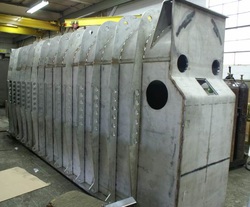
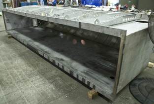
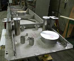
The large welded rectangular vacuum vessel and top plate required pre-machining of piece parts, weld sequencing and fixturing to minimize or mitigate weld distortion, and post-weld machining of the large 38.5" x 205" seal surfaces. On both the vacuum vessel and the top plate, the need to maintain reasonable thicknesses, while combating the forces imposed under vacuum, required numerous welded stiffeners. The many inches of weld metal needed to attach these stiffeners acts to distort and shrink the metal around it. These effects were mitigated by Meyer Tool by using fixturing during welding to counteract these effects and by sequencing the welds to reduce distortion. Even so, to meet the seal surface requirements on the top plate and vacuum vessel, both had to be final machined after welding. The 205" length of the cryomodule exceeded the length of even our large Giddings & Lewis boring mill. Our machinists, however, are well versed in dealing with such small obstacles and machined these large parts in multiple set-ups.
The magnetic shielding was supplied by ANL to Meyer Tool for installation. The magnetic shielding was laser cut to prints based on the 3D model of the cryomodule assembly. Like the previous rectangular cryomodule fabricated by Meyer Tool for ATLAS, the magnetic shielding is installed directly to the inside surfaces of the rectangular vacuum vessel and the vacuum vessel top plate. A system of welded threaded studs and batten strips are used to hold the magnetic shield tightly to the inner surfaces. Due to limitations in magnetic shield sheet sizes and other vendor fabrication limitations, the magnetic shielding consists of multiple panels that must be fit with overlaps to maintain the shielding effect. Meyer Tool technicians installing the magnetic shielding are trained to avoid cold working the shielding during installation or at any time in handling.
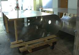
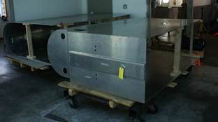
In the previous rectangular cryostat Meyer Tool built for ATLAS, the thermal shield was fabricated from ETP copper. However, in discussions with ANL regarding cost saving opportunities, the large shield required by the new cryostat and the relative cost of the copper vs. aluminum materials emerged as an opportunity for savings. (For a more detailed discussion of this topic see "Heat Shields: Materials and Cost Considerations.") It was determined that aluminum thermal shields were suitable for this application and further that an alloy more suitable for forming, with poorer thermal properties, 5052, still met the heat transfer requirements in this application. The shields are a welded fabrication, fabricated from laser cut and formed components based on the 3D model. The shields are cooled by liquid nitrogen running through stainless steel trace tubing. The stainless steel tubing is brazed to copper blocks that act as heat sinks. The copper blocks, with indium tinned faces to improve conduction, are mechanically fastened to the shields.
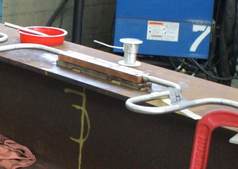
The superinsulation blankets consisting of double aluminized mylar with a spun bound polyester spacer material were located at 15 layers on the string side of the vacuum vessel and top plate thermal shield and 35 layers on the exterior side. Meyer Tool fabricates its own superinsulation blankets utilizing materials we specify. We have the in-house capability to fabricate superinsulation blankets 84" x 141" to thicknesses as required. Due to the large size of the thermal shields being covered by the superinsulation blankets, multiple blankets were made and spliced, with 5-layer interleaving between blankets. Templates were used to locate and make cutouts in the blankets for penetrations and supports. All blankets were pre-made prior to final assembly. Blankets were supported and hung on the thermal shields using a system developed by Meyer Tool.
Assembly of the system at Meyer Tool will begin shortly. The components, which so far are meeting their dimensional requirements, will be fit together. The integrity of the 3D model so far has proved reliable, so we are expecting the parts to fit with minimal hiccups.
Mark Kedzie and Mike O’Toole presented a poster at the recent CEC-ICMC2011 conference in Spokane, WA. They have graciously supplied us with the poster and pre-print of the paper associated.
