Call: 708-425-9080
FABRICATION TIPS
Recommendations - Lessons Learned - Technical Insights
#01 - DESIGN FOR WELD DISTORTON
|
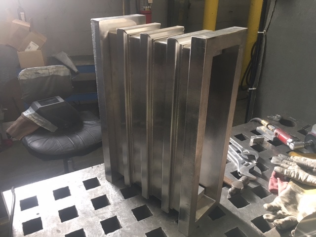
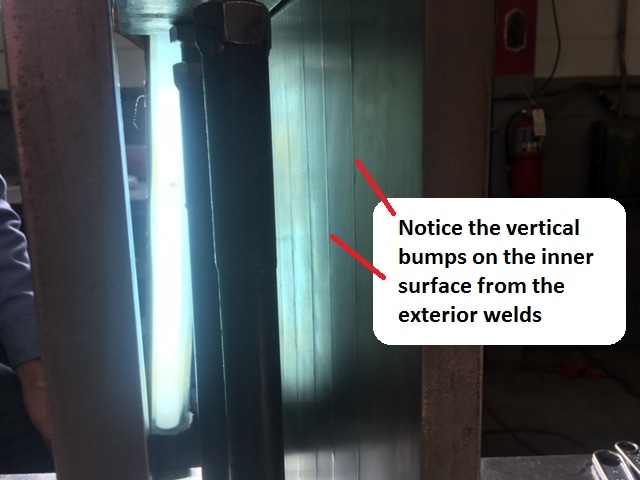
Here we have a 16ga Stainless Steel shell with water channels welded to the exterior. We are experts at minimizing weld distortion, but parts will always distort to some degree.
You can see that the channel welding leaves slight bumps on the interior. If this is a problem for your design, then thicker shell material should be used or it will add costly grinding and polishing to the job. |
#02 - WELDED FEATURES SHOULD NOT BE USED AS ALIGNMENT DATUMS
|
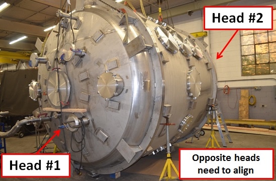
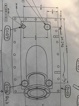
The heads on either end of this vessel must be aligned relative to one another. The ports on one head need to be concentric and parallel to the ports on the opposite side.
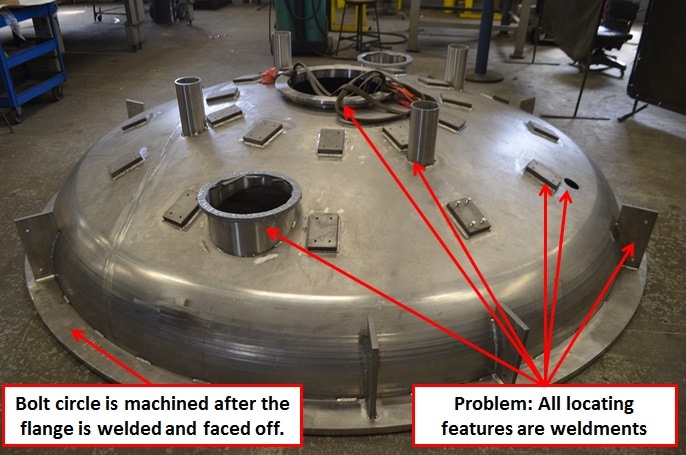
The final production drawing calls for the ports to be held to true position locations of 0.030". The trick to this inspection is the fact that the heads are symmetrical and round with no fixed locating features other than the various weldments. Pendicularity, concentricity, true position, and flatness of a welded feature can vary by up to 1/16" or more. This would make it impossible to accurately identify the final location of welded ports down to 0.030". One should always think about the order of operations that is occuring during production process to ensure that there will always be a machined datum that can be used to set a true "Zero" by which all other fetures can be evaluated. In this case the outer bolt circle would make a good datum and it would be ideal if that were machined first. If neccessary, holes can be drilled purely for location purposes. Otherwise, a block can be welded to the vessel and a locating hole cold then be welded to the block. This way the block can be removed without adding features to the head. |
#03 - EXCESSIVELY TIGHT TOLERANCES COST MONEY
It is important to consider tolerances and surface finish requirements specified on your drawings. Meyer Tool pays attention to the details so if you specify razor thin tolerances and tell us that you need to hit them, then we will do what it takes to meet your requirements. Other shops may quote you a price assuming that they can get away with giving you something less. That is not how we do business. We will always work with you to point out the various design features, tolerance changes, and component alternatives available that will optimize your design for fabrication.
ADDED POST-WELD MACHINING TIME
Over tolerancing a dimension can force us to perform unnecessary final machining operations after welding which adds time to your job and cost to your project. If you can accept the tolerances we can hold after welding, save yourself some cost by loosening the tolerances.
SPECIAL TOOLING EXPENSES
In some instances, the only way to hit very tight tolerances is for us to purchase custom tooling and drill bits. We often have to go so far as to fabricate our own custom tooling. Save yourself a few bucks and open up the tolerances so that standard tooling sizes can be utilized.
EXTRA POLISHING TIME
We deal with many different types of seal surface and flange requirements on the various pressure, vacuum, and cryogenic assemblies we build. Over tolerancing a seal surface finish can add costly hours to a job. The larger the surface area, the more time it will take to achieve the desired finish. Consider the type of seal you are using before you specify the surface finish requirement.
EXTRA MACHINING FIXTURING EXPENSE
As tolerances get tighter it becomes more and more important to hold the parts very still during machining. Excessive tolerancing will force us to have to beef up our fixturing designs and possibly slow down our run times. Doing so will add unneccessary cost to the project if the tolerances are not critical.
EXTRA MACHINING SETUP TIME
In order to hit tight tolerances on some assemblies it becomes necessary to go back and forth between welding and machining multiple times as certain areas become inaccessible for post-weld machining. The additional setup time for multiple operations can add up over the course of a job.
EXPENSIVE OUTSIDE OPERATIONS
There are some part geometries that require specialized equipment to complete like deep hole drilling, honing, boring, and electropolishing. Excessive tolerancing on complex geometry can make the costs increase dramatically as the expenses of outside machining, as well as transportation, have to be accounted for.
#04 - WORKING WITH CERAMIC FEEDTHROUGS
|
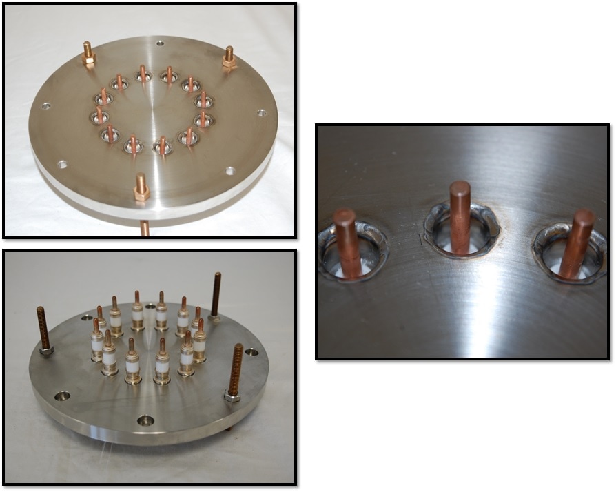
CERAMIC FEEDTHROUGH OVERVIEW
A ceramic feedthrough is a component frequently used in vacuum applications. The feedthroughs that allows you to transmit electricity across the vacuum or pressure barrier. The feedthrough consists of a copper rod surrounded by a ceramic core with a thin Stainless Steel outer shell. It is the thin Stainless Steel outer shell that gets welded to a flange or cover and the weld completes the vacuum or pressure seal. CERAMIC FEEDTHROUGH TIPS 1. It is good practice to always leak test every feedthrough before you do any welding. Even though they are leak tested at the factory, we occasionally run into leaks inside the feedthroughs themselves. They are a real pain to remove and replace once they are welded in place. 2. Size every hole to each specific feedthrough. We try to only have 0.001" to 0.003" of clearance between the feedthrough and the flange that it welds into. Sometimes the feedthrough diameters can vary quite a bit. The greater the gap, the more thermal stress is imparted into the ceramic core, and this increases the likelihood of cracks forming in the feedthrough. You want to have as tight a fit as possible so that the I.D. of the hole can support the ceramic feedthrough against both thermal and structural stresses. |
#05 - ACCOUNT FOR MATING PARTS IN THE ASSEMBLY
|
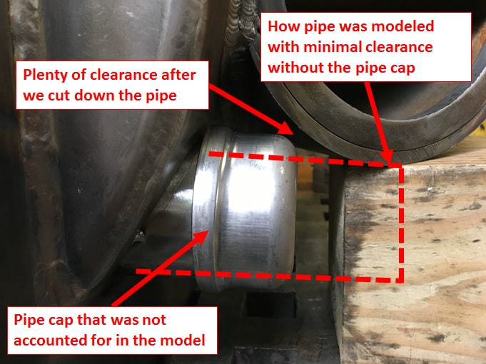
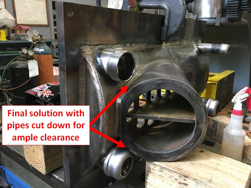
We occasionally run into issues related to not including common or off-the-shelf parts in the model of an assembly. This occasionally leads to clearance issues as the presence of these parts is not accounted for when laying out port locations.
It is always good design practice to include models of mating parts in the CAD model of the assembly to ensure that proper clearances are being accounted for in the model. We recently had an issue in which the design of a weldment did not account for the installation of some threaded pipe caps. These pipe caps were supplied later on in the project by the customer, and were not part of our scope so we did not have a way of catching the issue sooner. This issue could have been caught much earlier in the process if they were part of the CAD model and drawing package. Accounting for these off-the -shelf parts would have prevented production delays as we had to stop work and communicate back and forth with our customer to resolve the problem. |
