Call: 708-425-9080
Vacuum Chamber Design: Weld Joint Design
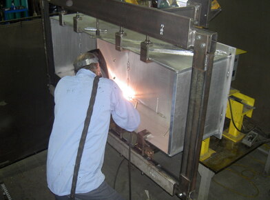 Proper location and selection of weld details is key to proper vacuum chamber design.
Proper design of vacuum chambers encompasses a number of important factors. One key to design and fabrication of a reliable chamber is understanding weld joint requirements and how they differ from pressure vessels and atmospheric tanks. Elsewhere on the website we discuss the issue of virtual leaks. One of the major causes of virtual leaks discussed was poor weld joint design techniques. The following article will be devoted to the issue of design and construction of welded joints to ensure proper performance of your vacuum system.
When designing or constructing a vacuum system, the following points need to be observed:
The following pictures represent both correct and incorrect practices for various styles of weld joints commonly used in vacuum chamber construction:
Butt Welds
When designing or constructing a vacuum system, the following points need to be observed:
- Full penetration welds should be utilized wherever possible to avoid pockets where volumes of gas or contaminants can be trapped.
- Utilize single pass welds if possible, to avoid trapped volumes that could be generated with multi-pass welds.
- Welds should always be made on the vacuum side of the joint.
- If for structural reasons double welds are required, allow for an easy path to flow gas from the joint. This could be in the form of a machined hole between the two welds, or a discontinuous weld on the non-vacuum side.
The following pictures represent both correct and incorrect practices for various styles of weld joints commonly used in vacuum chamber construction:
Butt Welds
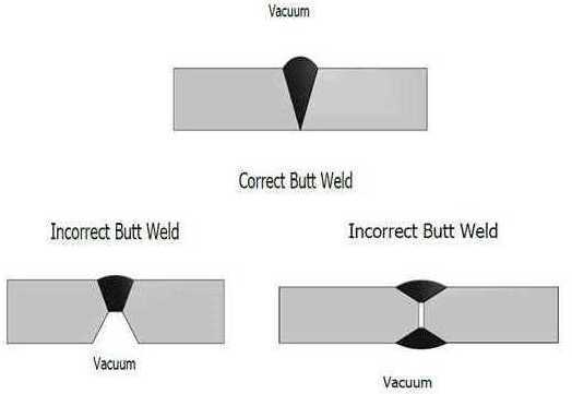
The correct style butt weld uses full penetration welds while incorrect style butt welds leave a pocket for contamination or a trapped volume between the two welds.
Lap Welds
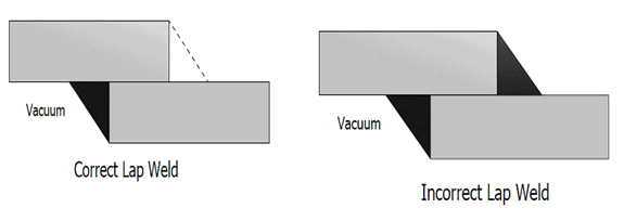
The correct style lap weld uses a full continuous weld at the vacuum side. If more structural strength is required, a skip weld can be added to the non vacuum side. The incorrect style lap weld uses two continuous welds on both the vacuum and non vacuum sides or a single weld on the non vacuum side leaving a trapped volume for gas and contaminants.
Corner Welds
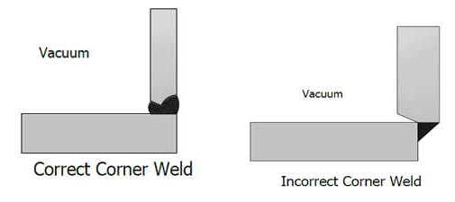
The correct style corner weld has the two sides that meet to form the corner flush with each other, and uses a full penetration weld. The incorrect style corner weld has one side overhanging the other at the weld joint, leaving a trapped volume for gas and contaminants.
Tee Welds
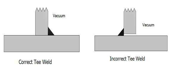
The correct style tee weld uses a full continuous weld at the vacuum side. If more structural strength is required, a skip weld can be added to the non vacuum side. The incorrect style tee weld uses two continuous welds on both the vacuum and non vacuum sides or a single weld on the non vacuum side leaving a trapped volume for gas and contaminants.
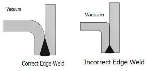
Edge Welds
The correct style edge weld uses full penetration welds where the two sides meet. The incorrect style edge weld has an elongated section where the two sides meet without a full penetration weld. This leaves a pocket for contamination, or leaves a trapped volume between the two surfaces.
These are just a few examples of weld styles that you may encounter during the design of a vacuum system. This by no means covers all the possibilities, but by using the basic concepts described here you will increase your success for a properly operating vacuum system.
Proper vacuum weld design is just one way Meyer Tool applies our Reduce Project Risk Process to ensure our customers' benefit from the best engineering and fabrication practices. Meyer Tool has more than 50 years of experience manufacturing vacuum vessels and components. Our experience spans a wide range of materials, processes, and project sizes. Whether you’re building a single prototype or need production manufacturing support for your unique vacuum application, Meyer Tool’s engineering and manufacturing team approaches each challenge using our Reduce Project Risk Process to support your needs.
Working on a project that requires design and manufacturing expertise?
Give us a call at 708-425-9080 or fill out our RFQ form to get started!


