708-425-9080
Meyer Tool & Mfg.
  • Services
    • Engineering Services >
      • Pressure Vessel Design
      • Vacuum Chamber Design
      • Cryogenic System Design
    • Machining Services >
      • CNC Milling
      • Lathe Turning
    • Welding Services >
      • ASME Code Welding
      • Aluminum Welding
      • Brazing and Soldering
      • Precision Welding Services
    • Assembly / Testing Services >
      • Helium Leak Testing
      • Pneumatic Pressure Testing
      • Hydrostatic Pressure Testing
      • Electrical Wiring / Sensor Testing
      • Cold Shock Testing
      • Precision Cleaning
      • Dye Penetrant Testing
  • Products
    • Vacuum Products >
      • Custom Vacuum Chamber >
        • Custom Aluminum Vacuum Chamber
        • Custom Stainless Steel Vacuum Chamber
        • Custom Exotic Material Vacuum Chamber
      • Custom Combination Pressure and Vacuum Chamber
    • Pressure Products >
      • Custom ASME Code Pressure Vessel
      • Non ASME Code Pressure Vessels
      • Custom ASME B31.3 Piping Systems
    • Cryogenic Products >
      • Custom Cryostats / Dewars >
        • Custom Aluminum Cryostats / Dewars
        • Custom Stainless Steel Cryostats / Dewars
      • Custom Cryogenic Distribution Boxes / Cold Boxes
      • Custom Heat Exchangers
      • Custom Cryogenic Thermal Shrouds and Shields
    • Machined Products >
      • Precision Mechanical / Electrical Assemblies
      • Custom Precision Machined Parts
      • Radio Frequency Components
    • MLI - Multi Layer Insulation
  • Experience
    • Customers / Industries >
      • Oil and Gas Industries
      • Aerospace Industry
      • Nuclear Industry
      • Coatings Industry
      • Semiconductor Industry
      • Astronomy Telescope Industry
      • Engineered Diamonds Industry
      • National Laboratories
      • Research Universities
      • Advanced Industrial Process Customers
      • CBD and Essential Oils
    • Customer Testimonials
  • Learning Center
    • Fabrication Tips
    • Newsletters >
      • Newsletter Signup
      • Newsletter Archive
    • Articles >
      • Custom Fabrication General Interest
      • Custom Cryogenic Technology
      • Custom Vacuum Chambers
      • Custom Pressure Vessels
  • About
    • Celebrating 50 Years
    • Why Us?
    • VIdeo Archive
    • Photo Gallery
    • Careers
  • Contact
    • Newsletter Signup

Call: 708-425-9080

Picture
more articles
Picture

​Welding Thin Walled Components to Thicker Sections

PictureMachining a weld relief groove
A common occurrence in the fabrication of vacuum and cryogenic components is the need to weld a thin walled tube or the cuff of a bellows element to a flange or other component of significantly greater thickness. Welding components of significantly different thicknesses when one of the components is very thin (less than 0.13”) can be challenging if proper selection of the weld detail is not made.

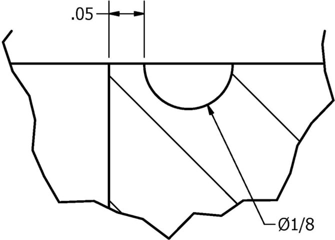
​When designing the weld detail between thin to thick components it is always important to match the thickness of the two parts that you are welding together.  This is often achieved by machining a weld relief groove (example, Figure 1) in the component to which the thinner component will be welded.  The goal of this technique is to get the thicker and the thinner components to dissipate heat in at a similar rate near the weld location.  The ability of the components to dissipate the heat of welding is proportional to the area available. Therefore, parts with more material thickness near the weld area will require more heat (voltage input from the welder’s foot pedal) to form a weld puddle.  However, adding more heat adversely affects the thinner component, such as a thin walled tube, causing such problems as burning through the thin wall.

​A weld relief groove detail which helps match the thermal properties of the two weld areas, will greatly reduce the chances of a weld failure.

Picture
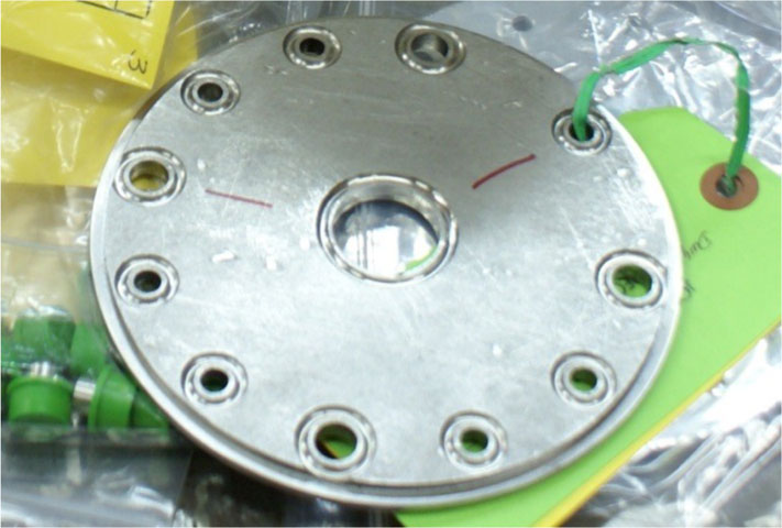
Weld Relief Groove for 0.035"w Tube
Even with a weld relief groove detail that matches the thicknesses of the two components, welding a thin component can be difficult.  It is often advantageous to make the matching wall of the weld relief groove detail slightly thicker than the wall thickness of the thinner walled member.  For example, if a tube wall thickness is 0.035” then a groove thickness of 0.050” would be very effective as seen in Figure 2.  This extra thickness allows the welder to arc to the weld relief groove wall, which will not melt at the same rate as the thin walled tube.  Since the weld groove wall thickness is only slightly larger than the thin walled tube, the heat to form a good weld puddle will not cause the problem discussed above.

Picture
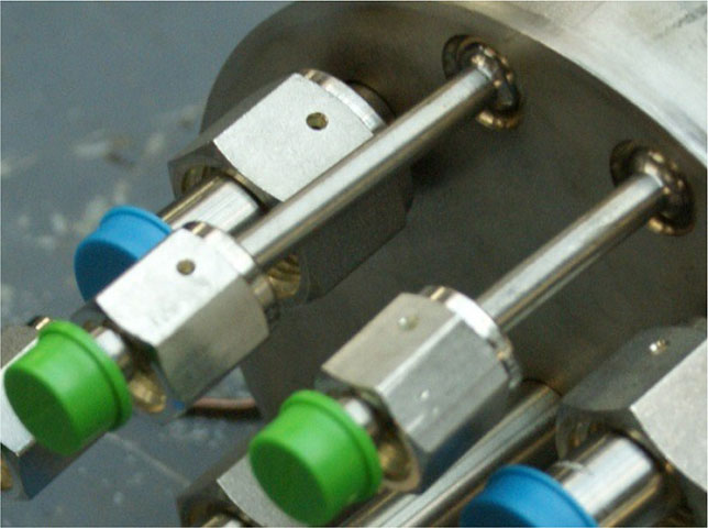
Welded Thin Walled Tube
However it does allow some slight variation in heat to allow the welder more control during welding.  Using weld relief groove details is a very effective way to ensure controllable helium leak tight and pressure tight welds. At Meyer Tool, this is one of the myriad of essential details we pay attention to while continuing to provide the lowest total cost of ownership to our customers.
​

Company Information

About Meyer Tool
Careers
Newsletter

Proud Member

Picture

Contact Us

Phone: 708-425-9080
Fax: 708-425-2612
Address: 4601 W. Southwest Highway, Oak Lawn, IL, 60453
​
​Request a Quote

Links

Home
Services
Products
Experience
Education
​Contact
Why Meyer Tool?

Stay Connected

© COPYRIGHT 2022. ALL RIGHTS RESERVED.