Call: 708-425-9080


Welding Basics: The Fillet Weld
|
Fillet welds and groove welds are the two most common types of weld configurations that Meyer Tool sees on our customers’ prints and that we use in our own designs. The fillet weld is used either by itself or in conjunction with a groove weld.
The strength of a fillet weld is determined by its effective area, which is the product of its throat thickness and length (See Figure 1). The ASME Section VIII B&PV Code Division specifies the required throat of a fillet weld in standard weld sketches or formulas in Section UW. However, in standard drawing practice per ANSI/AWS A2.4, it is the leg of the fillet weld that is specified, not its throat (See Figure 2). |
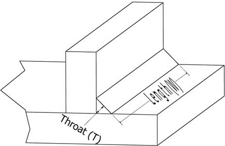
Figure 1 Fillet Weld, Throat and Length
|

Figure 2 Fillet Weld Callout
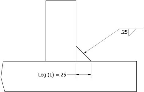
Figure 3 Throat and Leg Relationship
|
When determining the leg size to specify based on the required throat thickness, the fillet weld is considered to be an isosceles triangle. The throat thickness bisects the isosceles triangle, splitting the single triangle into two right triangles with the throat thickness on one side and the leg of the fillet weld being the hypotenuse. Thus the leg of the fillet weld is found to be L = T/COS(45) or as commonly approximated L= T/(0.7). (See Figure 3).
|