Call: 708-425-9080
Understanding Weld symbols – The groove weld
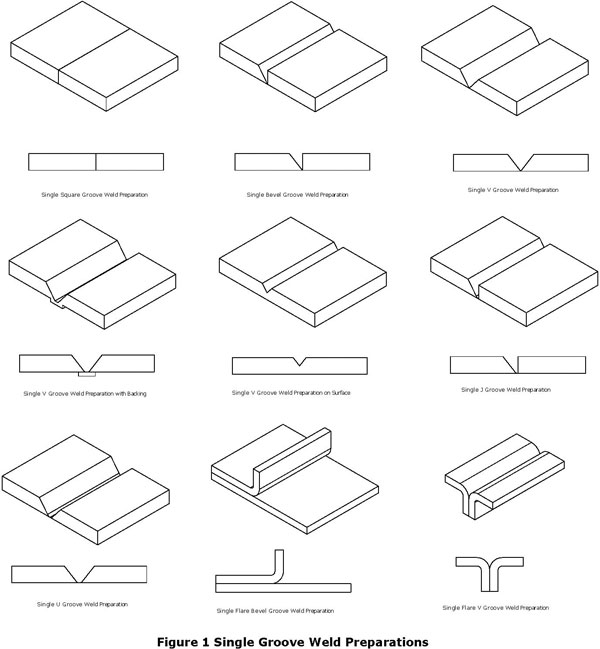
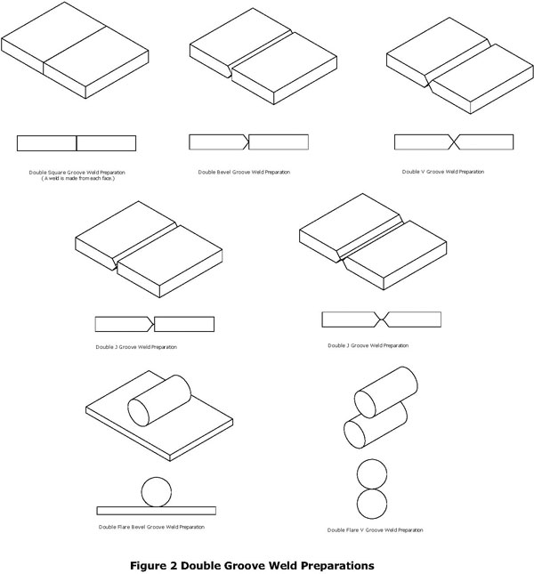
A groove weld is defined in the American Welding Society (AWS) AWS A3.0 Standard Welding Terms and Definitions as “A weld in a weld groove on a workpiece surface, between workpiece edges, between workpiece surfaces, or between workpiece edges and surfaces.” A weld groove is defined as “A channel in the surface of a workpiece or an opening between two joint members providing space to contain weld metal.” Groove welds fill the space made between sections of the workpiece. AWS A3.0 defines nine (9) types of single groove welds and seven (7) types of double groove welds. (Figure 1 and Figure 2). With the exception of square groove welds and flare groove welds, all groove welds require the removal of metal from one face (single groove) or both faces (double groove) of the workpieces. This joint preparation is in the form of a V, J, or U shaped cross-section. The joint preparation is for penetration of weld filler metal, either partially or fully through the workpieces.
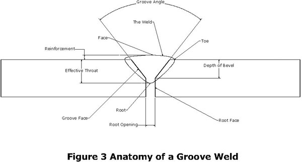
All the different types of groove welds contain similar features. The anatomy of a typical groove weld is illustrated in Figure 3.
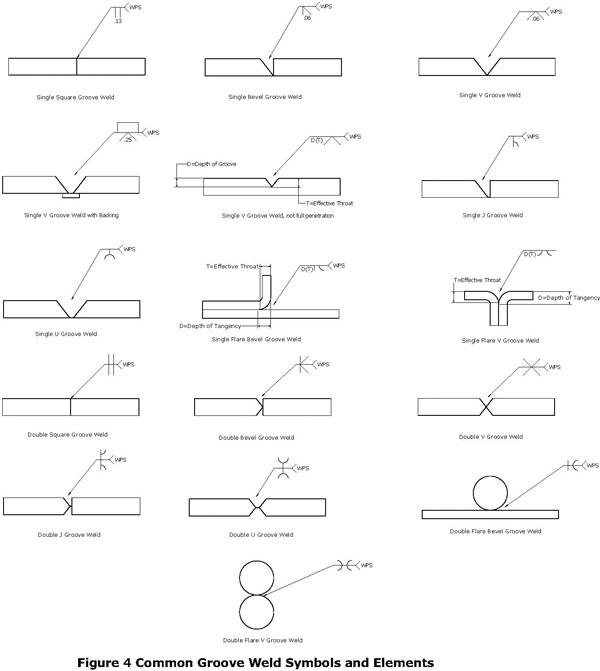
Like the basic fillet weld symbol, the groove weld symbol consists of a reference line, an arrow line, the tail, Weld Procedure Specification (WPS) information, and the appropriate groove weld symbol. Groove weld symbols can be much more complex than fillet welds symbols. The various basic groove weld symbols are shown in Figure 4. The preparation and groove weld types can be combined in various combinations that fit the physical reality of the workpieces. Groove welds can also be combined with other types of welds such a fillet welds.
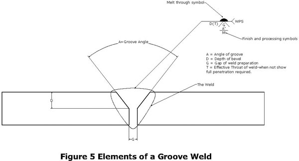
The elements of the groove weld symbol are shown in Figure 5. Like all welds symbols, the reference line is always drawn horizontally, it contains the weld type information and connects the arrow line and the tail. The arrow line points to the weld location. The underside of the reference line is referred to as the arrow side, weld symbols drawing on this side of the reference line are placed to the arrow side of the components; weld symbols located above the reference line are place on the components to the side opposite the arrow. The tail is actually an optional element and contains information regarding the weld. At Meyer Tool we use the tail to indicate at minimum the Weld Procedure Specification (WPS). The WPS identifies the procedures and parameters that the welder uses to accomplish the weld. Notes and other information on the weld can be included in the tail. At the juncture of the reference line and tail, a circle indicates the fillet welds goes entirely around the feature the arrow line is pointing at. Commonly applied to circular features, this instruction is not limited to them. A darkened flag at the juncture of the reference line and tail indicates the weld is to be performed in the field.
The elements of the groove weld symbol are shown in Figure 5. Like all welds symbols, the reference line is always drawn horizontally, it contains the weld type information and connects the arrow line and the tail. The arrow line points to the weld location. The underside of the reference line is referred to as the arrow side, weld symbols drawing on this side of the reference line are placed to the arrow side of the components; weld symbols located above the reference line are place on the components to the side opposite the arrow. The tail is actually an optional element and contains information regarding the weld. At Meyer Tool we use the tail to indicate at minimum the Weld Procedure Specification (WPS). The WPS identifies the procedures and parameters that the welder uses to accomplish the weld. Notes and other information on the weld can be included in the tail. At the juncture of the reference line and tail, a circle indicates the fillet welds goes entirely around the feature the arrow line is pointing at. Commonly applied to circular features, this instruction is not limited to them. A darkened flag at the juncture of the reference line and tail indicates the weld is to be performed in the field.
In Figure 5, G represents the gap between the work pieces to be joined, this is also referred to as the root opening. This opening is used to provide access for the welding electrode and improve penetration of the weld to the workpieces. When the weld gap alone will be insufficient to allow for penetration, for example as the workpieces become thicker, the workpieces are angled. As shown in Figure 5, the groove angle A, is the angle between the two workpieces. A bevel angle exists when only one of the workpieces is angled, as in a single bevel weld. The depth of the groove is represented by D, in Figure 5. The effective throat, T is indicated in parenthesis in the weld symbol. This element is only shown when the weld is not to be full penetration and represents the desired penetration depth of the weld. Just like the fillet weld, the face of a groove weld can be required to be flat, convex, or concave. If the face requires finish processing it could be Chipped (C), Ground (G), Hammered (H), Machined (M), Rolled (R), or Peened (P).
Drawings are the language of fabrication. Like learning a second language, our employees are trained to interpret and translate these symbols into physical reality. The correct understanding and interpretation of the specialize language of weld symbols by our engineers and weld technicians is just one of the many ways that Meyer Tool ensures we Reduce your Project Risk to help you achieve the lowest total cost of ownership.
Drawings are the language of fabrication. Like learning a second language, our employees are trained to interpret and translate these symbols into physical reality. The correct understanding and interpretation of the specialize language of weld symbols by our engineers and weld technicians is just one of the many ways that Meyer Tool ensures we Reduce your Project Risk to help you achieve the lowest total cost of ownership.
