Call: 708-425-9080


Understanding Weld Symbols - The Fillet Weld
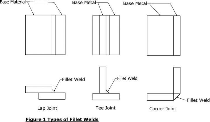
A fillet weld is defined in the American Welding Society (AWS) AWS A3.0 Standard Welding Terms and Definitions as “A weld of approximately triangular cross section joining two surfaces approximately at right angles to each other in a lap joint, T-joint, or corner joint.” (Figure 1).
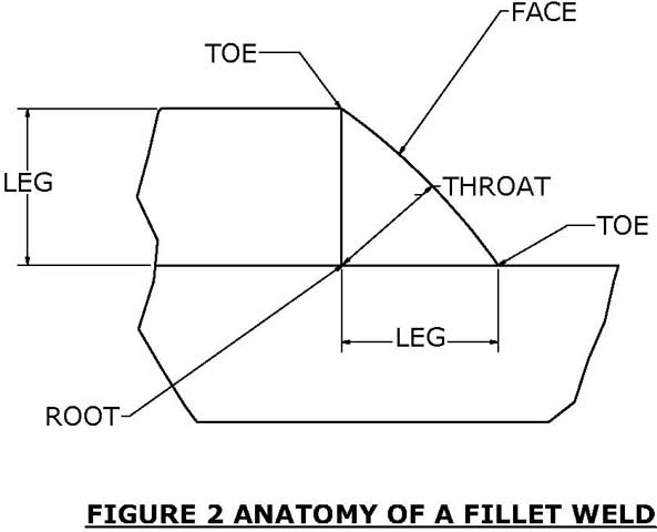
A fillet weld consists of the legs, the toes, the face, the throat, and the root (Figure 2). The throat of a fillet weld, which is used in calculating its strength, is defined as the distance between the root and face of the weld. The leg of a fillet weld is used to specify its size in the weld symbol.
The basic fillet weld symbol consists of a reference line, an arrow line, the tail, Weld Procedure Specification (WPS) information, and the fillet weld symbol including leg size. Some of the more common optional elements of a fillet weld symbol are shown in Figure 3.
The reference line is always drawn horizontally, it contains the weld type information and connects the arrow line and the tail. The arrow line points to the weld location. The underside of the reference line is referred to as the arrow side, weld symbols drawing on this side of the reference line are placed to the arrow side of the components; weld symbols located above the reference line are place on the components to the side opposite the arrow. The tail is actually an optional element and contains information regarding the weld. At Meyer Tool we use the tail to indicate at minimum the Weld Procedure Specification (WPS). The WPS identifies the procedures and parameters that the welder uses to accomplish the weld. Notes and other information on the weld can be included in the tail. The fillet weld symbol is represented as a triangle. The leg size of the fillet weld is place to the left of the fillet symbol. Most, but not all fillet welds are of equal legs. When the legs are not equal the leg sizes are indicated for example by 1 x 1.25. At the juncture of the reference line and tail, a circle indicates the fillet welds goes entirely around the feature the arrow line is pointing at. Commonly applied to circular features, this instruction is not limited to them. A darkened flag at the juncture of the reference line and tail indicates the weld is to be performed in the field.
The reference line is always drawn horizontally, it contains the weld type information and connects the arrow line and the tail. The arrow line points to the weld location. The underside of the reference line is referred to as the arrow side, weld symbols drawing on this side of the reference line are placed to the arrow side of the components; weld symbols located above the reference line are place on the components to the side opposite the arrow. The tail is actually an optional element and contains information regarding the weld. At Meyer Tool we use the tail to indicate at minimum the Weld Procedure Specification (WPS). The WPS identifies the procedures and parameters that the welder uses to accomplish the weld. Notes and other information on the weld can be included in the tail. The fillet weld symbol is represented as a triangle. The leg size of the fillet weld is place to the left of the fillet symbol. Most, but not all fillet welds are of equal legs. When the legs are not equal the leg sizes are indicated for example by 1 x 1.25. At the juncture of the reference line and tail, a circle indicates the fillet welds goes entirely around the feature the arrow line is pointing at. Commonly applied to circular features, this instruction is not limited to them. A darkened flag at the juncture of the reference line and tail indicates the weld is to be performed in the field.
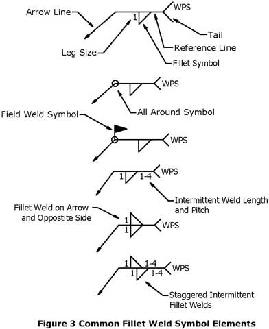
Fillet welds do not have to be continuous, the length and pitch between centers of an intermittent fillet weld are shown to the right of the fillet weld symbol. Fillets welds are not necessarily limited to one side of the components to be joined. Fillets welds can be made on both the arrow side and opposite side of the components. These fillet welds could be continuous or intermittent, if intermittent they can also be staggered.
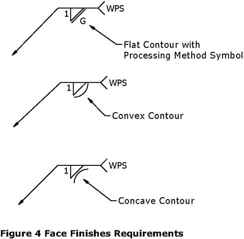
The face of a fillet weld can be required to be flat, convex, or concave. If the face requires finish processing it could be Chipped (C), Ground (G), Hammered (H), Machined (M), Rolled (R), or Peened (P).
The face of a fillet weld can be required to be flat, convex, or concave. If the face requires finish processing it could be Chipped (C), Ground (G), Hammered (H), Machined (M), Rolled (R), or Peened (P).
Drawings are the language of fabrication. Like learning a second language, our employees are trained to interpret and translate these symbols into physical reality. The correct understanding and interpretation of the specialize language of weld symbols by our engineers and weld technicians is just one of the many ways that Meyer Tool ensures we Reduce your Project Risk to help you achieve the lowest cost of ownership.