Call: 708-425-9080


Understanding Surface Finish and Surface Texture
Surface finish is a general term used to describe the condition of a material’s surface. A description of surface finish could include the surface’s texture (roughness, waviness, and lay), flaws, or even coatings such as electroplating, anodizing, or painting. The surface finish of manufactured products can vary significantly, depending on the materials and processes that are used to make the product. Effective communication of the surface requirements from the designer to the manufacturer is critical to ensuring the finished product meets the desired performance criteria. Often the consequences of omitting, incorrectly specifying, or misinterpreting surface finish requirements can substantially impact the performance and cost of the final product.
This article will focus on surface finish as would be of interest to the designer or user of vacuum or pressure vessels. We will discuss standard terminology and guidelines to consider during design and manufacturing to ensure the most effective surface characteristics are achieved. Discussion will be limited to the specifying of stainless steel plate or sheet material and specifying requirements to be achieved through manufacturing processes performed on stainless steel materials.
Finish, as it applies to stainless steel sheet and plate products, is a description of the finished surface characteristics for plate, sheet, and strip materials that are produced by various manufacturing processes. ASME SA-480/SA-480M Specification for General Requirements for Flat-Rolled Stainless and Heat-Resisting Steel Plate, Sheet, and Strip establishes standard guidelines for describing and identifying Finishes for plate, sheet, and strip. Plate is defined as material 3/16" and over in thickness and over 10" in width; sheet as material under 3/16" in thickness and over 24" in width; strip as cold-rolled material under 3/16" in thickness and under 24" in width. The ASME Standard uses a numbering system, commonly referred to as the Finish Number or Polish Number, for describing the types of finishes that are commercially available. For example, the Finish, or Polish, Numbers for sheet materials are: 1, 2D, 2B, Bright Annealed Finish, 3, 4, 6, 7, 8, TR Finish, and Special Finishes. Each Finish Number is described based on the manufacturing processes used to form and smooth the material. It should be noted that the Finishes and Polishes are distinguished by the plate, sheet, or strip material that they are describing, i.e. a No.1 Finish for sheet is different than a No. 1 Finish for strip.
Surface Texture is a quantitative surface characteristics of a material. ASME Y14.36M Surface Texture Symbols and ASME B46.1: Surface Texture (surface roughness, waviness, and lay) are established standards for communicating surface texture control requirements and defining surface texture properties. The surface texture of a material is defined by three primary properties: lay, waviness, and surface roughness of the material surface. Lay and waviness are surface irregularities that can be visually observed and measured. Lay is defined as the predominant direction of the surface pattern, which is typically determined by the manufacturing process being used. Waviness is defined as the more widely spaced component of surface texture. It is typically observed as recurrent deviations from the flat surface, and consists of the waviness width and waviness height. Lastly, the Surface Roughness is a calculated value which represents the ratios of the waviness height to the waviness length. Surface roughness is calculated by two means, the Roughness Average (Ra), which is the arithmetic average of the absolute values of the profile height deviations within the length being evaluated, and the Root-Mean-Square Roughness (Rq or RMS) which is the root mean square average of the surface profile height deviations within the length being evaluated. These two equations are shown below (Figure 1). Finally, the maximum height of the profile is defined as the vertical distance between the highest and lowest points of the profile, and provides a useful measure of the excess material that would need to be removed to achieve a smoother finish. In practice, these measurements and calculations are performed using a calibrated tool called a profilometer. Surface roughness is always specified in units of micrometers, also called a micron, (µm) or 1x10^-6m; or microinches (µin.) or 1x10^-6 in.
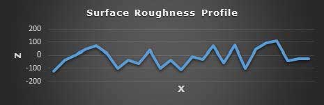
Figure 1 Surface Roughness as Measured by a Profilometer
As a designer or manufacturer, it is important to understand the surface roughness tolerances that can be obtained using various manufacturing processes. One should also consider the economics of choosing a final surface roughness. In general, surface texture selection should consider the interactions that the surface will have with the environment that it is exposed to. Considerations here could be aesthetics for a rough, painted, or polished finish; tribology (friction, wear, and lubrication) requirements; or thermal and electrical conductivity between surfaces. The golden rule for choosing a surface texture is understanding that cost will always increase when producing smoother and more polished textures, since more advanced tools, techniques, and time are required. As a designer, one would typical want to choose the roughest texture that satisfies the product goals, else cost may inadvertently be increased with little added value to the finished product.
It is also critical to properly communicate Surface Texture requirements on engineering drawings. The lay, waviness, surface roughness, and applicable tolerances are specified on drawings using the standard symbology in ASME Y14.36M. Figure 2 (below) demonstrates an example of this standard symbology. Although the standard symbology allows one to specify all texture parameters, it is quite common to see only the nominal roughness (Ra) specified.
It is also critical to properly communicate Surface Texture requirements on engineering drawings. The lay, waviness, surface roughness, and applicable tolerances are specified on drawings using the standard symbology in ASME Y14.36M. Figure 2 (below) demonstrates an example of this standard symbology. Although the standard symbology allows one to specify all texture parameters, it is quite common to see only the nominal roughness (Ra) specified.
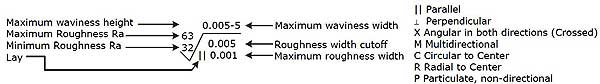
Figure 2 Specifying Surface Textures on Drawings
In this article, we have focused on and discussed variations in Surface Finish and Texture as defined by ASME Standards. In addition to ASME, other governing bodies have also made efforts to standardize surface specifications. For this reason, equivalence tables have been created for comparing across different specifications. Meyer Tool also has many experienced personnel that can help interpret your surface requirements.
At Meyer Tool, we emphasize that everyone involved in the manufacturing process be fluent in their understanding of surface finishes and textures. As one can see, there is a lot of information to be considered when selecting a surface finish and texture for your product. Communicating the surface requirements is just as critical as their functionality and economics. Ensuring that our customers understand and receive the most appropriate surface finish for their product is just another way that Meyer Tool helps to reduce project risk and our customers achieve the lowest total cost of ownership.
References
ASME Y14.36M Surface Texture Symbols
ASME B46.1 Surface Texture (Surface Roughness, Waviness & Lay)
ASME SA-480/SA-480M Specification for General Requirements for Flat-Rolled Stainless and Heat-Resisting Steel Plate, Sheet, and Strip
ISO 1302 Geometrical Product Specifications (GPS) - Indication of Surface Texture in Technical Product Documentation
Kalpakjian, Serope, and Steven R. Schmid. Manufacturing processes for engineering materials. 4th ed. Upper Saddle River, N.J.: Prentice Hall, 2003. Print.