Call: 708-425-9080


Understanding ASME UG-45
Editor’s note: This “how to” article was written by Jake Rumel, University of Illinois Class of 2010. Jake interned with Meyer Tool in 2009 and then came back to work for us full time after receiving his engineering degree. Meyer Tool promotes a learning culture and we have trainees in all our departments. Jake gets a lot of new stuff thrown at him while learning the theoretical and practical aspects of cryogenic, vacuum and pressure equipment manufacturing. When I noticed that UG-45 had been re-written, I felt we had a perfect opportunity to both further Jake’s familiarity with a confusing section of the ASME Code and inform our readers. Good job Jake, thanks.
I am an engineer currently learning the ASME Code for Pressure Vessels here at Meyer Tool. In the past, the ASME Code Section VIII Paragraph UG-45 about the minimum nozzle neck thickness has been a paragraph that has needed multiple re-readings in order to fully grasp all of the requirements. However, over the years, Section VIII Paragraph UG-45 has gone through several revisions. These revisions have not changed the content or the general rules of this section. Instead, they have been an attempt to clarify a confusing set of requirements for the thickness of nozzles in an ASME code pressure vessel.
The latest version of the ASME Code (the 2010 Ed.) has made use of a few simple formulas and a table to help clarify Section VIII Paragraph UG-45. The formulas attempt to provide a quick association between the various different factors that can affect the thickness requirements of the nozzles. Older versions of the code would describe whether to take the max or the min between different factors in the same subparagraphs in which the factors were defined. This would require multiple readings of all subparagraphs in order to make sure that all relationships between factors were realized.
The addition of the table in Section VII Paragraph UG-45 functions mainly to help speed up the application of the code requirements. Older versions refer the reader to ASME B36.10 or ASME B36.10M in order to determine the minimum thickness for standard wall pipe. The newest version defines in the paragraph what the minimum thickness for standard wall pipe is in table UG-45 and relates it to the newly added formulas.
While the method for explaining the requirements of Section VIII Paragraph UG-45 have improved over the years, the actual implementation can still be rather tricky. The calculation of ta references the equations from UG-27 and UG-28 for internal and external pressure vessel, but it does not stress that the nozzle properties are supposed to be substituted for the vessel properties. tb1 and tb2 are calculated using the vessel shell properties in the same formulas, however the Paragraphs UG-27 and UG-28 are not referenced. To make these realizations, Non-Mandatory Appendix L which contains some examples is very useful. Unfortunately, the Non-Mandatory Appendix L in the 2010 Ed. has not been updated to reference the changes to Paragraph UG-45. It makes no mention of using the new formulas and defines requirements based on the 2007 Ed. format. This requires a comparison between the 2007 and the 2010 Editions in order to make the examples in the
Process for Calculating Minimum Nozzle Thickness
|
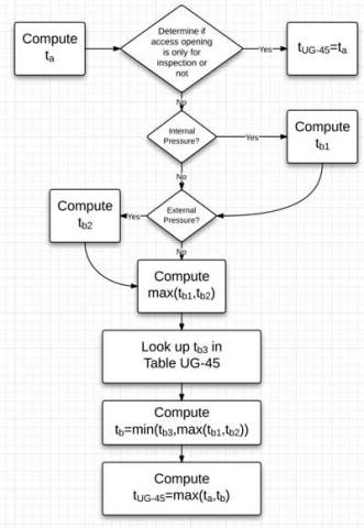
In order to help clarify, here is a summary and a flow diagram (Figure 1.) of the steps to using Section VIII Paragraph UG-45. To start calculating the nozzle neck thickness, you must first determine the whether the access openings and openings are for inspection only. If they are, then the nozzle neck thickness is determined by the simple relationship:
tUG-45 = ta Where ta is the minimum required thickness determined from Paragraphs UG-27 (Thickness of Shells under internal Pressure) and UG-28 (Thickness of Shells under External Pressure). This calculation uses the properties of the nozzle for the calculation of the minimum thickness (the internal/external pressure of the nozzle, the nozzle radius, the joint efficiency, and the maximum stress the nozzle material can handle). This must also consider the effects of external forces and moments as defined by Paragraph UG-22. Also, note that the shear stresses caused by the loadings called out in Paragraph UG-22 shall not exceed 70% of the allowable tensile stress for the nozzle material. For nozzles that are not for inspection only, tUG-45 = max(ta, tb) Where ta is the same as defined above and tb is determined by the equation tb = min[tb3, max(tb1, tb2)] Here tb1 and tb2, are calculated using the properties of the shell (the internal/external pressure of the vessel, the shell radius, the joint efficiency, and the maximum stress the shell material can handle) in the same formulas as ta. The difference is that tb1 is calculated for when the shell has an internal pressure, and tb2 is calculated when the shell has an external pressure. Naturally, if these pressures do not exist, then tb1 and tb2 do not apply. Finally, tb3is determined using the Table UG-45 which gives the minimum wall thickness for standard wall pipe. This simple method for determining the minimum wall thickness of a nozzle can often be tough to decipher if one is not familiar with ASME Code’s presentation of information style. That’s why continuing efforts to make the code information more accessible to those trying to learn the code is always very much appreciated. |