Call: 708-425-9080
Thermoacoustic Oscillations
 Thermoacoustic oscillations can develop in tubes which connect a cryogenic reservoir to room temperature.
Thermoacoustic oscillations can occur when a temperature gradient is established in a gas filled tube. Thermoacoustic oscillations that are produced when a tube, closed at the warm end, extends from room temperature to a region at liquid helium temperatures are often referred to as Taconis oscillations, after K.W. Taconis, who encountered these oscillations while studying the properties of 3He / 4He mixtures at the Kamerlingh Onnes Laboratory in the 1940s. The largest amplitude will be obtained when the open end of the tube is placed in cold helium vapor just above the surface of the liquid. Thermoacoustic oscillations normally occur at the lowest resonant frequency of the tube. The lowest resonant mode in a tube that is closed at one end will have a zero (anti-node) in amplitude at the closed end and a peak amplitude (node) at the open end, yielding a wavelength equal to four times the length of the tube. The speed of sound in cold (5K) helium vapor is about 130 m/s. Assuming that the tube is about 1m long, the frequency of oscillation should be:
f = c/λ = 130 ms-1/4m = 32 Hz
Thermoacoustic oscillations occur because as gas at the bottom of the tube cools its density increases and the pressure at the top of the tube falls. Gas from the bottom of the tube then expands into this region of low pressure. In most cases the oscillation is damped and a stable pressure gradient is established. However, if the tube diameter, temperatures, and gas properties fall within the right range, then sustained oscillations can be produced.
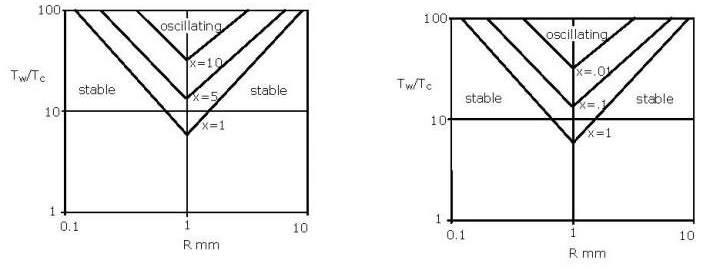
Thermoacoustic oscillations can produce a large heat load. Many observers have noted a marked increase in the boil-off rate from their dewar when a thermoacoustic oscillation is established. A thermoacoustic oscillation transfers heat from the warm end to the cold end because gas absorbs heat from the walls as it expands at the warm end and gives up heat to the walls as it is compressed at the cold end. For this reason thermoacoustic oscillations are normally to be avoided. Both experimental and theoretical efforts have been made to better understand the conditions under which these oscillations can occur. Early work by Rott was later extended by Yazaki and by Gu. The result are a set of curves illustrated by Figure 1. Here, regions of stability and oscillation are plotted as a function of ratio of the warm end to cold end temperatures TW/TC and the scaled radius R = r (1000mm/L)1/2 where r is the actual tube radius and L is its length. Families of curves are obtained for different valves of x = LW/LC; the ratio of the warm to cold lengths of the tube. If the values of TW/TC, and R place a system inside the V-shaped region (above the line for that value of x), then the thermoacoustic oscillations are expected.
 Liquid Helium Dip Stick
Thermoacoustic oscillations are obtained over the widest range of conditions when the temperature ratio between the warm and cold ends TW/TC is large, and for this reason they are often encountered in liquid helium systems. However, thermoacoustic oscillations may also be obtained in liquid (and slush) hydrogen, liquid oxygen and liquid nitrogen systems. Fortunately structures such as dewar necks are generally too large in diameter to support thermoacoustic oscillations. Thermoacoustic oscillations are more likely to occur in small diameter tubes such as wave guides, transfer lines and valve stems which extend from the warm end to the cold end of a cryostat. Thermoacoustic oscillations can also occur when a vessel of cryogenic fluid is connected through relatively long and narrow fill and vent tubes. The liquid hydrogen cells used as targets in many accelerator laboratories fall into this category.
There are a number of strategies to eliminate thermoacoustic oscillations when they do occur. The answer may be as simple as removing a liquid transfer line when it is not in use. When tubes such as waveguides must extend from the warm end to the cold end of a dewar it is common practice to drill a small hole at the warm end (inside the cryostat) to reduce the likelihood that oscillations will develop. Figure 2 indicates that oscillations are obtained over the widest range of conditions when x = 1 (equal warm and cold lengths). This suggests that increasing the effective length of the warm side by adding volume (making x>>1) or reducing the volume of the warm side by introducing an annular wire in the tube (making x<<1) are two strategies to eliminate thermoacoustic oscillations. Changing the heat sinking of tubes such as fill and vent lines can also eliminate thermoacoustic oscillations by changing the ratio of warm to cold volumes.
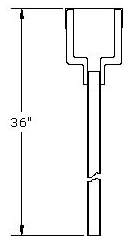
While thermoacoustic oscillations are generally to be avoided, they can be useful as a level probe in the liquid helium "dip stick". While a simple length of metal tubing closed on the top by the user's thumb will suffice, Gaffney and Clement described a more elaborate version. Here a long 0.125" tube is terminated with an inverted reducer which is covered by a rubber membrane. The reducer results in larger amplitude vibrations, while the rubber membrane closes the end of the tube while still transmitting vibrations. The rubber membrane also prevents frozen air or moisture from plugging the tube. To measure the depth of liquid helium in a dewar, the "dip stick" is first lowered to make contact with the bottom of the dewar and the height is noted. As the tube is withdrawn, Taconis oscillations will start or sharply increase in amplitude when the bottom of the tube clears the surface of the liquid. (The surface of the liquid acts as a "soft" closure at the bottom of the tube.)
We normally think of a thermoacoustic oscillation as a mechanical oscillation, or sound wave, driven by a temperature difference. This oscillation transfers heat from the warm side to the cold side of the system. It is possible to run the process in reverse; to drive a mechanical oscillation in order to generate a temperature difference and transfer heat from the cold side to the warm side. This is the principle behind pulse tube refrigerators.
Thermoacoustic oscillations are just one of the pitfalls that can be encountered when building cryogenic equipment. Even advanced numerical models will not always accurately predict when a system will oscillate. The engineering department at Meyer Tool is dedicated to helping our customers avoid these pitfalls when they can be foreseen, and finding practical solutions when they cannot. Working with our customers to overcome unexpected difficulties is one of the ways in which we Reduce Project Risk to achieve the lowest total cost of ownership.
References:
Measurements concerning the vapour-liquid equilibrum of solutions of He3 in He4 below 2.19°K, K. W. Taconis, J. J. M. Beenakker, A. O. C. Nier and L. T. Aldrich, Physica 15, 733 (1949)
Thermally driven acoustic oscillations, part III, N. Rott, Journal of Applied Math. and Physics, 26, 43 (1975)
Stability limit for thermally driven acoustic oscillation, T. Yazaki, A. Tominaga and Y. Narahara, Cryogenics, 19, 393 (1979)
Experimental Verification of Stability Characteristics for Thermal Acoustic Oscillations in a Liquid Helium System, Youfan Gu and Klaus D. Timmerhaus, Advances in Cryogenic Engineering, 39, 1733 (1994)
Liquid Helium Level‐Finder, John Gaffney and J. R. Clement, Rev. Sci. Instrum. 26, 620 (1955)
Further Reading:
An Investigation of Thermally Driven Acoustical Oscillations in Helium Systems, J. D. Fuerst, Fermilab-Conf-94/424
Thermal Oscillations, excerpted from Experimental Cryophysics, F. E. Hoare, L. C. Jackson, N. Kurti (1961)
Thermoacoustic Oscillations, D. Fahey, Wave Motion & Optics (2006)
What is thermoacoustics? A brief description, with technical details and citations, Los Alamos National Laboratory, (2004)


