Call: 708-425-9080
Sudden Loss of Isolation Vacuum in Cryogenic Liquid Dewars
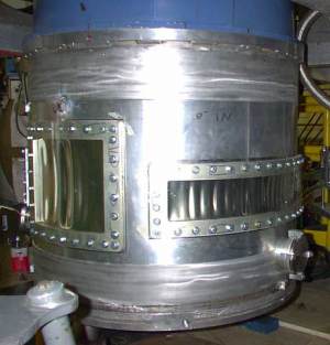
 This helium dewar houses a superconducting magnet, making these thin metal windows all the more hazardous.
Storage dewars for cryogenic liquids generally have an isolating vacuum jacket to reduce the conduction heat load. If that isolation vacuum is lost suddenly, due to structural failure or operator error for example, then there will be a sudden increase in the heat load on the cryogenic liquid. If the vacuum jacket of a liquid helium dewar is suddenly broken by air then nitrogen and oxygen will condense on the helium vessel and freeze. The resulting heat load on the liquid helium dwarfs those typically encountered in dewar and cryostat design. When helium boils it expands by a factor of five and as the cold vapor warms it expands further. If an adequate flow path is not provided, the pressure in the dewar will rise until the dewar bursts. Liquid hydrogen and liquid neon will also condense and freeze air and these dewars are also subject to a high heat flux if the liquid vessels are exposed to air.
The sudden or catastrophic loss of isolation vacuum is usually the worst case scenario for a liquid helium, hydrogen, or neon dewar and this is the condition that the relief path must be designed to handle. In dewars housing superconducting magnets or RF cavity, a quench (loss of superconductivity) can also deposit a significant heat load into dewar’s cryogenic liquid. A worst case scenario in which a sudden loss of isolation vacuum is accompanied by a quench is not unlikely. Examples of this are a rise in liquid temperature due to the rise in pressure as the dewar vents causing a superconducting magnet to quench. Loss of liquid level will cause a magnet or RF cavity to quench. If the loss of isolation vacuum is due to failure of the vacuum vessel then the same event that caused the vessel to fail may cause a quench. To size the relief path for a dewar housing a superconducting magnet or RF cavity the heat loads due to a possible simultaneous quench and loss of isolation vacuum must be considered.
Loss of isolation vacuum events can and have occurred in a number of ways. Dewars used in nuclear and particle physics experiments often have thin metal windows to allow particles to enter and exit with minimal energy. These windows can fail due to corrosion or relatively minor mechanical impact. Thin windows are particularly at risk if the dewar also houses a high-field magnet which is capable of turning loose tools into projectiles. The inadvertent opening of a large valve or a material handling accident can also cause a sudden loss of isolation vaccum.
 The total pressure in the dewar will be the sum of the relief valve pressure as well as any additional pressure drops along the relief path.
To size a relief path we start with the heat load anticipated during a loss of isolation vacuum incident. For design purposes the values used are typically in the range of 16kW/m2 to 38kW/m2 for uninsulated surfaces and around 6 kW/m2 for surfaces insulated with multilayer insulation (MLI). These are fairly conservative values in that they are at the high range of those measured. These values are supported by measurements made on helium vessels with the vacuum spoiled by air. Spoiling the vacuum of a helium dewar with helium gas results in a lower peak heat load because the heat load is due to conduction and convection only. These are peak heat loads which occur early in the loss of vacuum event. As a layer of frozen air accumulates it serves as additional insulation. While the above values are measured for helium they are often assumed for other liquids.
The total pressure in the dewar will be the sum of the relief valve pressure as well as any additional pressure drops along the relief path.
Given the heat load it is possible to calculate the peak mass flow. A pressure relief device with the required capacity can be selected. Since relief valves are sized for volumetric flow, it is necessary to know the density and therefore the temperature of the gas. The evolving vapor will be at the boiling temperature of the liquid and it is normally possible to estimate the temperature rise of the vapor along the relief path. Very often the worst case assumption is made; that the vapor has warmed to ambient temperature and the relief path is sized accordingly. This is erring on the side of caution, however, it does not make the relief path sizing dependent on heat transfer estimates.
Sizing the pressure relief device, usually a relief valve or a rupture disk, is a critical issue, however, to predict the peak internal pressure that the dewar will experience the entire relief path must be considered.
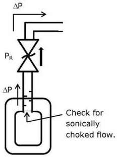
The pressure drops across fittings and piping runs must be added to the relief pressure to obtain the total pressure in the dewar. Care must be taken if the relief path includes corrugated metal hose because the pressure drop in corrugated hose can be much greater that that that expected in smooth wall tube or pipe with the same ID. To correctly estimate the pressure drop at any point where the flow area is reduced it is first necessary to determine whether or not the flow is sonically choked.
The piping which connects to the liquid space at the top of the dewar spans the liquid temperature and ambient temperature and we often wish to place baffles in that piping to limit thermal radiation to the cold volume. If that piping is part of the relief path, and it usually is, then care must be taken to avoid creating an unintended flow impedance. The usual practice is to use a series of staggered, half-round baffles to block thermal radiation without severely restricting gas flow. We are aware of instances in which a set of full-round heat shields, installed in the relief path of a dewar, left the liquid volume with an entirely inadequate relief path.
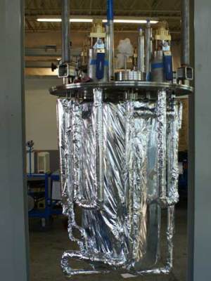
 MLI will greatly reduce the heat flux to a cryogenic vessel during a loss of isolation vacuum event, but only if it remains in place.
One final consideration: MLI, to be effective as a multilayer heat shield, must be applied loosely to maintain spacing between layers. In a truly catastrophic loss of vacuum event the MLI is unlikely to remain attached to surfaces inside the dewar and the actual heat load may be much greater than anticipated. If the 6 kW/m2 figure has been used to size the relief path then the liquid vessel should be insulated in a manner that will insure that the insulation remains in place even under conditions of strong turbulence.
We have seen recent intriguing work on this topic at the CEC/ICMC 2013; paper 3EOrE2-04,Modeling the Pressure Increase in Liquid Helium Cryostats after Failure of the Insulating Vacuum. Our reading of the paper is that it presents evidence that the current methods and simplifications for estimating gas helium gas loads due to loss of insulating vacuum in air are overly conservative and further study will lead to numerical models and methods that provide more economical solutions to sizing relief valves and systems.
Providing an adequate relief path is a critical step in designing a dewar, particularly when the fluid in question is liquid helium, hydrogen, or neon. The condensation of air on vessels containing these liquids can result in a large heat flux and a correspondingly high flow rate in the relief path. Nitrogen, oxygen, and argon vessels will experience a lower heat flux, but still must be provided with an adequate relief path. Anticipating every off-normal event that could add gas to the relief line, and every feature that could contribute to the flow impedance, is key to sizing the relief line correctly. Anticipating the unexpected is one more way that Meyer Tool strives to Reduce Project Risk to ensure our customers achieve the lowest total cost of ownership.


