Call: 708-425-9080


Specifying Nozzle Ports on Cylindrical Vessels
We often receive hand sketches or rough CAD sketches of vacuum or pressure vessels. These sketches often employ a variety of methods for specifying location and tolerance of nozzle ports. This article suggests a simple standard method of specifying this information on cylindrical vessels. Specification of nozzle locations on rectangular vessels will be addressed in a future article.
|
|
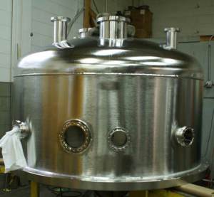
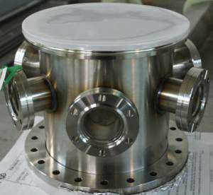
Figure 1. Regardless of size the same method can be used to specify nozzle location and tolerances.
Step 1.
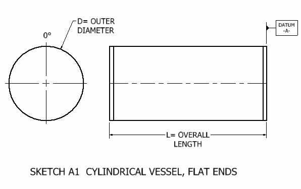
a. For a cylindrical vessel with flat ends define vessel major dimensions, the centerlines of the vessel, and one end as a datum. (Sketch A1). Define one centerline axis as the zero degree axis.
a. For a cylindrical vessel with flat ends define vessel major dimensions, the centerlines of the vessel, and one end as a datum. (Sketch A1). Define one centerline axis as the zero degree axis.
|

|
b. For a cylindrical vessel with domed ends define the vessel major dimensions, the centerlines of the vessel, and one end as a datum point. (Sketch B1). Define one centerline axis as the zero degree axis.
Step 2.
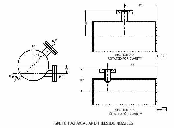
a. If the nozzle is an axial or hill side nozzle, define the distance from the vessel datum to the nozzle centerline, X (Sketch A2).
Step 2.
a. If the nozzle is an axial or hill side nozzle, define the distance from the vessel datum to the nozzle centerline, X (Sketch A2).
|
|
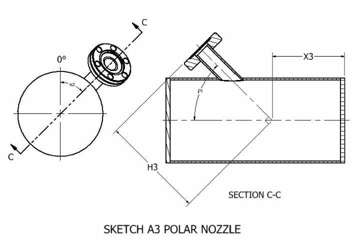
b. If the nozzle is a polar nozzle, define the distance from the vessel datum to the intersection of the nozzle centerline with the vessel centerline (the nozzle’s focal point), X (Sketch A3).
Step 3.
a.If the nozzle is an axial nozzle or hill side nozzle, define the distance from the centerline of the vessel to the nozzle flange face, H (Sketch A2).
b.If the nozzle is a polar nozzle, define the distance from the line, intersecting the focal point and perpendicular to the nozzle centerline, to the nozzle flange face, H (Sketch A3).
Step 4.
a.If the nozzle is an axial nozzle, define the angle from vessel zero degree axis to the centerline of the nozzle, ɑ1 (Sketch A2).
b.If the nozzle is a hill side nozzle, define the distance from the vessel’s second centerline to the nozzle centerline, Y (Sketch A2).
c.If the nozzle is a polar nozzle, define the angle from vessel zero degree axis to the centerline of the nozzle, ɑ2 and the angle from the vessel centerline to the centerline of the nozzle, ρ1 (Sketch A3).
Step 5.
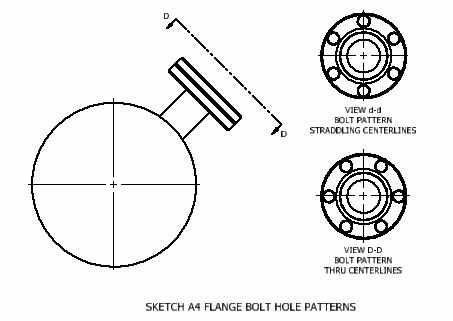
a. Specify whether the nozzle flange bolt hole pattern “straddles” the flange centerlines (Sketch A4 View d-d) or that the nozzle flange bolt hole pattern passes through the centerline (Sketch A4 View D-D).
Step 3.
a.If the nozzle is an axial nozzle or hill side nozzle, define the distance from the centerline of the vessel to the nozzle flange face, H (Sketch A2).
b.If the nozzle is a polar nozzle, define the distance from the line, intersecting the focal point and perpendicular to the nozzle centerline, to the nozzle flange face, H (Sketch A3).
Step 4.
a.If the nozzle is an axial nozzle, define the angle from vessel zero degree axis to the centerline of the nozzle, ɑ1 (Sketch A2).
b.If the nozzle is a hill side nozzle, define the distance from the vessel’s second centerline to the nozzle centerline, Y (Sketch A2).
c.If the nozzle is a polar nozzle, define the angle from vessel zero degree axis to the centerline of the nozzle, ɑ2 and the angle from the vessel centerline to the centerline of the nozzle, ρ1 (Sketch A3).
Step 5.
a. Specify whether the nozzle flange bolt hole pattern “straddles” the flange centerlines (Sketch A4 View d-d) or that the nozzle flange bolt hole pattern passes through the centerline (Sketch A4 View D-D).
Step 6.
Standard, as welded tolerances for vacuum chambers and thinner walled pressure vessels are generally in the order of +/-0.03” and 0.5 degree. Tighter tolerances are held by post weld machining critical features. The user should specify the necessary tolerances on their sketch.