Reducing Project Risk with New Technology
Step 3. Develop, in our Reduce Project Risk process focuses on process improvement. Process improvement is often the result of engineering and manufacturing team members collaboration, but sometimes it is the result of our empowered workforce embracing and leveraging the latest technology.
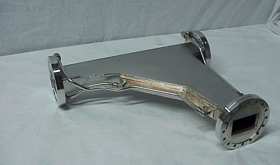
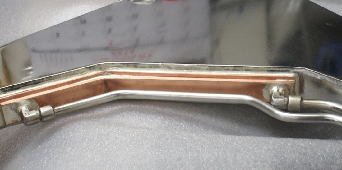
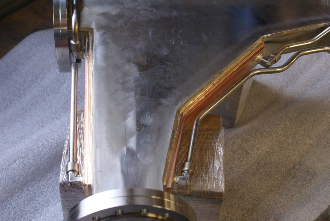
For almost twenty years we have provided a custom UHV stainless steel chamber with two OFHC copper cooling channels to meet a critical application in an e-beam accelerator used for medical sterilization. The two cooling channels penetrate through the chamber walls; with the braze between the stainless vessel and the copper cooling channels forming part of the vacuum boundary.
These chambers are built in batches of 2 or 3 approximately every other year. A stable process was developed to build these chambers, with incremental improvements over the years usually centering on improvements in documenting the process. Examples include transferring the 2D drawings to 3D models and using digital photography to transform a text-based traveler to a visually documented standard manufacturing procedure. This allowed us to maintain our learning curve on a product built in infrequent batches.
For this current batch of vessels our machine shop recognized that we had an opportunity to transform how the most difficult component of the vessel, the ‘hockey stick’ shaped inner cooling channel was machined. The vacuum boundary braze joint between the stainless steel chamber body and the cooling channels requires a precise 0.002” gap fit between the body and channel. For more information on braze joints at the vacuum boundary look at our article “Braze Joints at the Vacuum Boundary”. The vessel is a semi-rectangular chamber with an inlet port and two outlet ports. The layout is illustrated in Figure 1.
Historically the ‘hockey stick’ shaped copper channels were milled out of a rough formed block of copper in a combination CNC and manual machining by a master machinist. The interface between the copper channel and the opening in the stainless-steel body were custom fit to maintain the tight braze fit required.
Leveraging advanced CAM programming and the multi-axis capabilities of our 5-axis mill the multi-set up, arduous machining process for the upper portion of the copper channel becomes a single set up repeatable process. Improving quality, cycle time, and allowing us to control pricing during a time of rising costs. The video illustrates the difference old and new CNC technology.
Implementing our commitment to Reduce Project Risk involves not only applying our Process of Discover, Design, Develop, and Deliver to our customers' projects but also to discovering ways to improve our own internal manufacturing capabilities. Our customers from accelerator components to semiconductor demand the highest quality. Utilizing the latest in manufacturing technology to improve productivity and maintain quality is just one way we commit to achieving these goals.
How we apply our Reduce Project Risk Process to our own business processes to better fulfill our customer needs is an important aspect of how Meyer Tool implements continuous improvement. Meyer Tool has more than 50 years of experience manufacturing cutting-edge components and assemblies. Our experience spans a wide range of materials, processes, and project sizes. Whether you’re building a single prototype or need production manufacturing support for your unique components, Meyer Tool’s engineering and manufacturing team approaches each challenge using our Reduce Project Risk Process to support your needs.
Working on a project that requires manufacturing expertise?
Give us a call at 708-425-9080 or fill out our RFQ form to get started!


