Call: 708-425-9080


Pressure Relief for Vacuum Chambers
A vacuum chamber, as a sealed volume, has the potential to become pressurized. Most vacuum vessels are designed to withstand external pressure only and any internal pressure capacity is solely a consequence of the external pressure design. Vacuum chambers, whether evacuated chambers or the insulating jackets of cryogenic equipment, can be subject to failure modes that could pressurize the sealed volume. Consideration of the best method to reduce this project risk is fundamental to safe vacuum chamber design.
Examples of the potential sources of pressurization include:
There is almost always some source of possible pressurization. It is good design practice to include a pressure relief device on a vacuum chamber.
In recent years the issue of pressure relief for vacuum chambers has received increased scrutiny at the national laboratories due to the implementation of Federal Regulation 10 CFR 851. The Vacuum Systems Consensus Guideline for Department of Energy Accelerator Laboratories report interprets these regulations and offers direction on how they can be satisfied for many vacuum systems. This report splits vacuum chambers into three categories and treats each according to its associated risk. The categories are:
The report requires that vacuum vessels that are determined to belong to Category II and III be protected by pressure relief devices certified to ASME UV requirements.
We will limit our discussion to pressure relief devices for vacuum chambers that fall under the Category I criterion and Category II vessels where the customer requirements do not require an ASME certified device. Pressure relief devices for Category II and III vacuum chambers will be discussed in another article.
One of the most common pressure relief devices found on vacuum chambers is often referred to as a “vacuum seal off valve”. Variations of this device are produced by a number of manufacturers. These devices consist of a sliding plug, in some cases spring loaded, sealed by an o-ring. Internal vacuum holds the plug in its seat, but internal pressure causes the plug to slide out past the o-ring seal, relieving the pressure. These relief valves double as a vacuum pump-out port. An operator slides over the body of the valve and forms a vacuum tight seal by means of an o-ring. A handle on the operator allows the sealing plug to be withdrawn to pump the vessel down and then the plug is reinstalled before the operator is removed.
Examples of the potential sources of pressurization include:
- Many vacuum chambers are connected to a source of pressurized gas (dry nitrogen) to break the vacuum in the chamber and have the potential to be over-pressurized.
- In the case of liquid helium, hydrogen or neon dewars, small leaks to atmosphere may cause a build-up of frozen air over time. When the dewar warms up, the relatively sudden evaporation of frozen air can cause over pressure in the vacuum space.
- A breach of any sealed cryogenic storage dewar could lead to pressurization of the isolation vacuum space.
- Chambers which include water cooled devices or process gas lines have the potential to become pressurized.
There is almost always some source of possible pressurization. It is good design practice to include a pressure relief device on a vacuum chamber.
In recent years the issue of pressure relief for vacuum chambers has received increased scrutiny at the national laboratories due to the implementation of Federal Regulation 10 CFR 851. The Vacuum Systems Consensus Guideline for Department of Energy Accelerator Laboratories report interprets these regulations and offers direction on how they can be satisfied for many vacuum systems. This report splits vacuum chambers into three categories and treats each according to its associated risk. The categories are:
- Category I: Vacuum vessels in which the differential pressure across the vacuum can never exceed 15 psi.
- Category II: Vacuum vessels that are protected from credible failures that could create pressurization exceeding 15 psi through the use of engineering controls such as pressure relief devices.
- Category III: Vacuum vessels that are not or cannot be protected from credible failures that could create pressurization exceeding 15 psi.
The report requires that vacuum vessels that are determined to belong to Category II and III be protected by pressure relief devices certified to ASME UV requirements.
We will limit our discussion to pressure relief devices for vacuum chambers that fall under the Category I criterion and Category II vessels where the customer requirements do not require an ASME certified device. Pressure relief devices for Category II and III vacuum chambers will be discussed in another article.
One of the most common pressure relief devices found on vacuum chambers is often referred to as a “vacuum seal off valve”. Variations of this device are produced by a number of manufacturers. These devices consist of a sliding plug, in some cases spring loaded, sealed by an o-ring. Internal vacuum holds the plug in its seat, but internal pressure causes the plug to slide out past the o-ring seal, relieving the pressure. These relief valves double as a vacuum pump-out port. An operator slides over the body of the valve and forms a vacuum tight seal by means of an o-ring. A handle on the operator allows the sealing plug to be withdrawn to pump the vessel down and then the plug is reinstalled before the operator is removed.
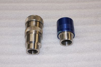
Figure 1 Two examples of simple pressure relief/pump-out valves and an operator. These valves are for welded installation. The external cover is removed to fit the operator.
|

|
A simple check valve may be used as a pressure relief device for a vacuum chamber. However, many check valves are “bubble tight” but not leak tight by vacuum standards and will not pass a helium mass spectrometer leak test.
On vacuum chambers which require pressure relief with higher volumetric flow capacity, such as the vacuum space for liquid helium dewars, the parallel plate relief valve is frequently encountered. This valve consists of a blank cover flange over a flange communicating with the vacuum chamber. The flanges are sealed by an o-ring. The outer flange is mounted with shoulder bolts or threaded rods and springs to provide a light load to reseat the plate should it lift. When these valves are installed on vacuum chambers providing the insulating jacket around a multilayer insulation (MLI) insulated vessel, the potential for plugging the relief valve with MLI in a catastrophic loss of vacuum incident is a concern. For that reason a perforated shield is placed at the entrance of the valve inside the chamber.
On vacuum chambers which require pressure relief with higher volumetric flow capacity, such as the vacuum space for liquid helium dewars, the parallel plate relief valve is frequently encountered. This valve consists of a blank cover flange over a flange communicating with the vacuum chamber. The flanges are sealed by an o-ring. The outer flange is mounted with shoulder bolts or threaded rods and springs to provide a light load to reseat the plate should it lift. When these valves are installed on vacuum chambers providing the insulating jacket around a multilayer insulation (MLI) insulated vessel, the potential for plugging the relief valve with MLI in a catastrophic loss of vacuum incident is a concern. For that reason a perforated shield is placed at the entrance of the valve inside the chamber.
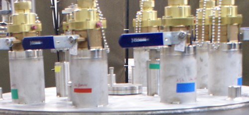
Figure 2 Parallel plate relief valves; installed
|
The pressure relief device on a vacuum chamber must be sized to handle the maximum flow of gas that could be created in any credible failure scenario. For chambers with no process gas lines, no water cooled devices, or no internal liquid vessels, this may be quite small. If evaluation of the credible failure modes confirms minimal pressure rise, simple cost effective pressure relief valves of the type discussed above are adequate. Understanding and ensuring the correct selection of pressure relief devices to protect your vacuum chamber investment is just one of the ways Meyer Tool Reduces Project Risk and provides our customers with the Lowest Total Cost of Ownership.
|
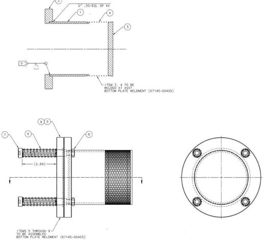
Figure 3: Drawing