Call: 708-425-9080
Multilayer Insulation—Part 2: Installation Techniques
|
In Part 1 we discussed what multilayer insulation is and how it is used in cryogenic applications to reduce thermal load or “heat leak”. In Part 2 we will discuss some of the techniques used when installing multilayer insulation on custom cryogenic equipment. (Please note this discussion relates only to low volume custom and semi-custom equipment and not production equipment, where investment in capital tooling may yield different conclusions.)
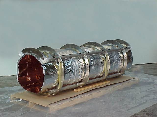
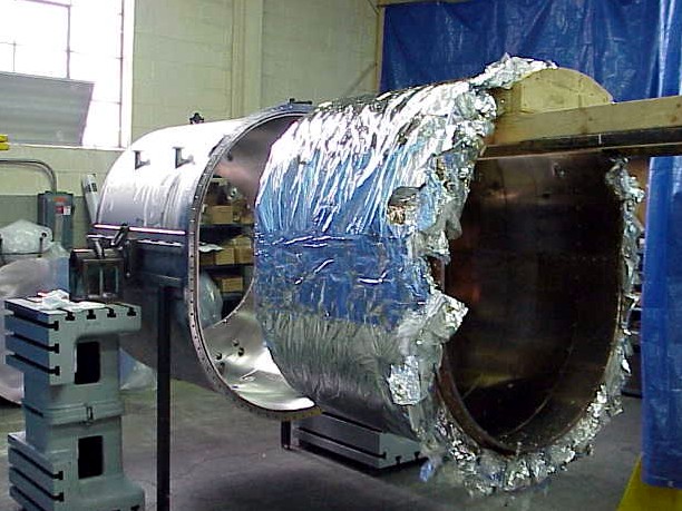
Copper Thermal Shield with Multilayer Insulation Blanket. When designing a system using multilayer insulation the engineer must understand that to achieve the calculated thermal load he is solely dependent upon the expertise of the installers. Thermal loads from improperly installed multilayer insulation can be orders of magnitude greater than anticipated. Thus proper training of installers in both the cause and effect of proper and improper technique and practical hands-on training to become familiar with what works is extremely important. Important Factors There are of course cases where installation cost versus performance is not a factor, but for most terrestrial-bound custom cryogenic equipment the following factors should be considered when installing multilayer insulation. Crinkled and perforated multilayer insulation, no spacer.
Common Elements Based on how multilayer insulation works as a multiple shield radiation barrier, spiral wrapping of individual layers on the object to be insulated would seem the best method of insulation. But for most instances of custom cryogenic equipment this would present practical difficulties. Part geometry and installation sequences don’t usually allow for this technique. When they do, this technique can be very time-consuming and labor-intensive, i.e., cost-prohibitive. Elements common to most pieces of custom cryogenic equipment that require the application of multilayer insulation are:
Practical Installation Techniques Discussion on approaches to insulating these common elements has to start with the most practical of questions: How do you get the multilayer insulation to stay on? All methods in some way compromise the effectiveness of the insulation blanket. The engineer must take these factors into account when estimating the system heat leak. |
One of the most common methods involves taping of the MLI blanket to the object. Another is to use “nails” or “spikes” attached to the object; the blanket is pierced to hold it in place. Velcro on the object and the innermost layer of the MLI blanket is sometimes used.
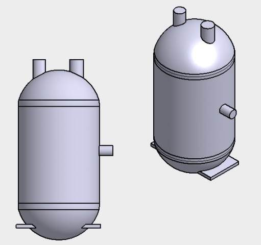
Figure 1. Simple Inner Vessel Configuration
Figure 1 shows a simple inner vessel to be insulated with a 15-layer MLI blanket.
One approach to insulating this vessel would involve the use of three main blankets and small custom fit patches at the support points and nozzles. First a single 15-layer blanket would be rolled to fit the cylindrical portion of the vessel; the circumferential length of this blanket would be made so as to allow a 2-inch overlap at the longitudinal seam. The blanket would be criss-cross cut at the location of the shell nozzle. The technician would install the blanket, piercing the nozzle pipe through the criss-cross cut on the blanket. The first longitudinal edge of the blanket would be peeled back, exposing the bottom 5 layers. The edge of these 5 layers would be taped directly to the cylindrical shell, typically using an aluminized mylar tape. The second longitudinal edge of the blanket would be pulled around to the first, with the technician making sure to maintain the correct layer density. The first 5 layers of this edge will have been removed in the overlap area and the second 5 layers will overlap the first 5 layers of the first edge and be taped to the blanket. The top 5 layers of the second edge would be removed as well as the middle 5 layers of the first edge. Thus 5 layers from each edge are interleaved and taped. Alternate techniques could include single layer interleaving or simple 5-layer overlap without removal. These have different effects on total heat leak and the balance between improved heat leak vs. installation labor cost must be considered.
Blankets for the top and bottom domed heads would be made. These blankets would have criss-crossed piercing for the nozzle locations and be cut for support locations. The blankets would also be designed to allow trimming and fitting for a 2-inch overlap with the shell blanket.
Gravity assists the technician in installation of the upper dome blanket. The blanket can be draped over the head, matching the criss-crossed piercings to the nozzle locations. The technician then trims the dome and shells blankets and, like the seam of the shell blanket, overlaps and interleaves the layers of the mating blankets. Key to this is not to compress the blanket at the intersection of the shell and dome.
The bottom dome is fabricated in much the same way, complicated by both gravity and the fact that the insulation is done in situ, so the support areas have to be cut and overlapped during installation.
The above is of course the relatively easy part of the insulation assembly. The more difficult areas are interleaving and fitting the difficult shell-to-nozzle, head-to-nozzle and support geometries. In these cases the technician fits and interleaves the shell and nozzle blankets, fitting and interleaving with utmost care to prevent gaps and maintain layer density.
The more complex the geometry the more difficult and time consuming the insulation process can be. Ensuring that this process is properly planned and executed is key to a building successful cryogenic component.
If this article was of interest to you, drop us a line and let us know. Your feedback will help us determine what type of content you would like to see in our newsletter and posted to the website.


