Call: 708-425-9080


Interference Fits in Manufacturing
Meyer Tool & Mfg., Inc. utilizes various manufacturing techniques to mate parts together during fabrication of the many unique projects built here. For parts that need the ability to be removed, threaded connections are typically used. Permanent connections can be achieved by welding (when joining similar metals) or brazing (when joining dissimilar metals). When these methods are unavailable or undesired, interference fits can be a reliable style of mating parts together.
Interference fits are held together using the stresses caused by pressure of the two materials pushing against each other. Meyer Tool typically uses interference fits for installing locating pins. The pressure caused by the interference fit must be greater than the tangential stress in the pin otherwise the pin would be able to be pulled out. This tangential stress is generally a function of the use of the component and your starting point. The pressure is related to the tangential stress () by the following:
Interference fits are held together using the stresses caused by pressure of the two materials pushing against each other. Meyer Tool typically uses interference fits for installing locating pins. The pressure caused by the interference fit must be greater than the tangential stress in the pin otherwise the pin would be able to be pulled out. This tangential stress is generally a function of the use of the component and your starting point. The pressure is related to the tangential stress () by the following:
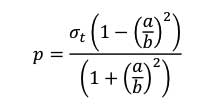
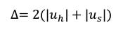
Where a is the radius of the pin, and b is the radius of the hole in the mating part. You can see that when the radius of the pin is very small while the radius of the mating part trends to infinity (as in the case of a pin in a large plate), then the pressure would be equal to the maximum tangential stress. With this pressure, you can now calculate the required increase in hole radius () and decrease in pin radius () with the following:
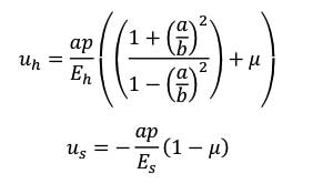
Where µ is the Poisson’s ratio, and the Es and Eh are the modulus of elasticity for each material. Again, if the mating part for the pin is very large then the difference between the hole and pin change in radius is only a factor of the modulus of elasticity of the material. Thus the interference required is obtained from the following:
With the required interference of the parts calculated, the correct dimensioning on the parts to ensure a proper interference fit can be established. Both ANSI B4.2 and ASME Y14.5 give guidelines for tolerancing interference fits. We will save this discussion for another article.
There are two common methods for installing parts with an interference fit connection. The first is to use a force greater than the maximum tangential stress described above. This can be difficult depending on the force required and has the potential to damage the components. The second method, usually a safer option, varies the temperature (through heating or cooling) between the parts to cause the material to expand or contract to a size that would allow the parts to slip past each other. Then, the parts would regain the interference as they expand or contract back to room temperature conditions. The temperature required depends on the amount of interference between parts and the thermal expansion coefficient of the material. Note: the thermal conductivity of the materials should also be considered when using this method since this will determine how fast the materials will go back to room temperature conditions. Cooling is often preferred to heating since heating can often cause unwanted distortion in the parts, but this depends on the materials involved.
While the concept of interference fits have been described primarily for installing locating pins, another more complex use of the concept is used in cryostat and cryomodule construction where strong, precise but low heat leak supports are required.
Two examples of such support posts are shown in Figures 1 and 2.
Figure 1 is an example is a re-entrant post. One of many such posts built by Meyer Tool in the early 1990s, this design utilizes two composite tubes and stainless steel and aluminum components to form a serpentine long heat leak path from the 4k cold mass to the 300K insulating vacuum vessel. The interference fits utilize both ID disks and OD rings resulting in extremely strong joints.
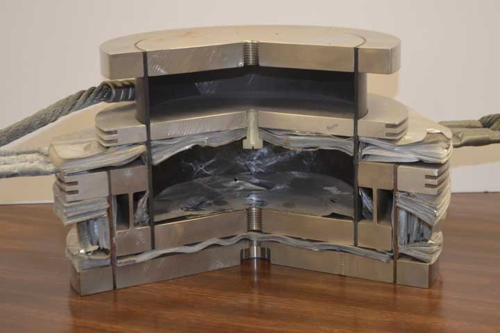
Figure 1. Cross-Section of Fermilab designed cryomodule re-entrant support post
Figure 2 is an example of the much more common single support post design. This particular photo is of a Cornell University design we recently built for Helmholz-Zentrum Berlin. These posts are actually in tension as they hang from ports located at the top of the cryomodule and cold mass containing SRFC cavities are suspended from them.
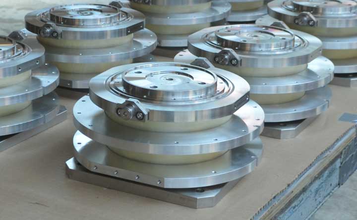
Figure 2. Cornell University cryomodule single tube support post
Discovering and defining customer goals, designing and developing robust manufacturing processes, and delivering unique and difficult assemblies is an everyday occurrence at Meyer Tool, part of our Reduce Project Risk process. Building support posts using proper sequencing, assembly techniques, and tooling ensure our customers lchieve the lowest total cost of ownership.