Call: 708-425-9080


Information on the ASME Code and DOE Pressure Safety Rules
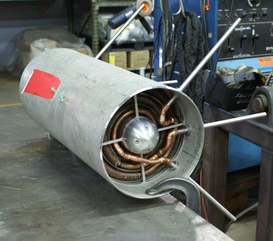 ASME U Stamped Liquid Helium/Liquid Hydrogen Heat Exchanger Pressure Vessel
The Department of Energy is requiring its subcontractors (e.g. the National Laboratories) to meet 10 CFR 851 Appendix A Part 4 for all new pressure vessels and pressure piping. Meyer Tool’s understanding is that all new Pressure Vessels are required to be built and stamped to the ASME Boiler and Pressure Vessel Code Section VIII and that all new Pressure Piping is to be built to the appropriate ASME B31 Piping Code, which in most cases would be B31.3 Process Piping. The only exceptions to ASME code vesssels and pressure piping are when the design falls outside the scope of the Codes. This article will provide some guidance to those unfamiliar with the Code for specifying an ASME Code Pressure Vessel.
The ASME Boiler and Pressure Vessel Code consists of twelve Sections. Section VIII contains the Rules for Construction of Pressure Vessels. Section VIII is further divided into three Divisions. Division 1 treats Vessels designed by rules and does not require a detailed evaluation of all stresses. Division 2 provides alternative rules for Vessel design and requires a much more detailed evaluation of stresses. Division 3 concerns alternate rules for construction of High Pressure Vessels (maximum allowable working pressure above 10,000 psig). The majority of pressure vessels are designed and built to the requirements of Division 1.
Division 1 is divided into three Subsections A (General Requirements), B (Methods of Fabrication) and C (Material Requirements), thirty-three Mandatory Appendices and twenty-two Non-mandatory Appendices. Together with references within the Subsections and Appendices to other Code Sections these comprise the rules for design and fabrication of a U (unfired pressure vessel) Stamped ASME Code Pressure Vessel. An important point to remember is the paragraphs of the Subsections are intertwined with recursive references and dependencies. Don’t make the mistake of reading any set of paragraphs in isolation.
Prior to the Subsections is the Introduction. The Introduction defines the Scope of Section VIII Division 1, both by identifying what types of vessels that specifically fall within the Division and by what types of vessels that do not. In our opinion the two most important statements within the Introduction are contained in paragraph U-1 (a)(3) and U-1(c)(2).
To paraphrase U-1 (a)(c), where a mandatory requirement or prohibition exists it must be followed by the designer or fabricator (i.e. Rules based). However where such guidance does not exist, engineering judgment consistent with the Division’s design philosophy may be used. This is worth stressing: a perfectly valid analysis may lead to a different result than a Division design formula or fabrication detail, however the Code requirement must be followed.
U-1(c)(2), basically states that while a given Vessel may not fall within the Scope of the Division, if it meets all the requirements of the Division, it may be U Stamped. This simplifies meeting the requirements of 10 CFR 851 Appendix A Part 4 when the Vessel does not fall within the Division Scope. For example, a vessel under 6 inches in diameter, which falls outside the Scope, can be U Stamped.
Subsection A “General Requirements” contains Part UG. Part UG’s title tells it all “General Requirements for All Methods of Construction and All Materials”. What makes the Code so difficult to those unfamiliar with it is that it really does contain “General Requirements”. So a set of paragraphs discussing a subject that appears to be totally unrelated to your vessel may have pertinent requirements buried in it. Part UG contains the most used paragraphs of the Division UG-27 though UG-53. These paragraphs contain or reference the design formulas you need to size a Division 1 Vessel. That is not to say that from your start in UG you won’t be making side trips to Part UW, Section II and the Appendices.
Some typical examples of oversights by those new to the Code are:
We could continue with examples for pages. The point is, of course, that to effectively use the Code, you need a good grasp of it as a whole.
Subsection B “Requirements Pertaining To Methods of Fabrication of Pressure Vessels” contains three parts Part UW (fabrication by Welding), Part UF (fabrication by Forging) and Part UB (fabrication by Brazing). A given Pressure Vessel may be fabricated by the use of one of these methods or by a combination of these methods.
The majority of Vessels U Stamped by Meyer Tool are fabricated to Part UW. We have, however, built Vessels solely fabricated to Part UF and in combinations of UW, UF and UB. For simplicity, we will confine our comments to Part UW.
Part UW contains requirements on Service Restrictions, non-destructive examination (NDE) requirements, joint efficiencies (used in Part UG design formulas) specific fabrication details for welded joints, and general welded fabrication requirements. Just like Part UG, these different topics are all interrelated. UW-2 Service restriction might dictate the type of weld required for a specific weld Category (see UW-3). This in turn may define the radiographic or other NDE requirements to be taken on the weld. The joint efficiency selected in Table UW-12 is then dependent on these factors.
Part UW contains specific weld joint details that both simplify and limit a designer’s choices. Many of these design details are overly conservative, especially in regards to vacuum vessel design. However, once again, if the Vessel is to be U Stamped these details are mandatory. Selection of the appropriate details is again dependent on the factors discussed in the previous paragraph.
Subsection C “Requirements Pertaining to Classes of Materials” consists of eight Parts. These Parts contain rules specific to certain classes of materials. The use of these Parts is, as implied, applicable only when the material covered by the Part is used. Of particular interest to those of us, like Meyer Tool, involved in the construction of U Stamped Pressure Vessels for use with Cryogenic liquids is Part UHA “Requirements for Pressure Vessels Constructed of High Alloy Steel”.
This Part discusses High Alloy Steels; for Cryogenic Pressure Vessels this means austenitic stainless steels, typically 304/304L or 316/316L. Of special interest to Cryogenic Pressure Vessels users and fabricators is paragraph UHA-51 pertaining to Impact Test Requirements. A summary of requirements follows for austenitic stainless steels.
The Mandatory Appendices address specific topics and should be reviewed by the designer and manufacture for applicability. The Non-mandatory Appendices address a number of useful topics and are worth review.
In order to begin an ASME Section VIII Division 1 design, the following information about ASME code pressure vessels should be known.
These items will open the discussion and interactive process with a firm like Meyer Tool. The result will be a fabrication ready design that will satisfy the requirements for an ASME Code U Stamped Vessel and thus 10 CFR 851 Appendix A Part 4 and, most importantly, your ASME code pressure vessel process needs.
The ASME Boiler and Pressure Vessel Code consists of twelve Sections. Section VIII contains the Rules for Construction of Pressure Vessels. Section VIII is further divided into three Divisions. Division 1 treats Vessels designed by rules and does not require a detailed evaluation of all stresses. Division 2 provides alternative rules for Vessel design and requires a much more detailed evaluation of stresses. Division 3 concerns alternate rules for construction of High Pressure Vessels (maximum allowable working pressure above 10,000 psig). The majority of pressure vessels are designed and built to the requirements of Division 1.
Division 1 is divided into three Subsections A (General Requirements), B (Methods of Fabrication) and C (Material Requirements), thirty-three Mandatory Appendices and twenty-two Non-mandatory Appendices. Together with references within the Subsections and Appendices to other Code Sections these comprise the rules for design and fabrication of a U (unfired pressure vessel) Stamped ASME Code Pressure Vessel. An important point to remember is the paragraphs of the Subsections are intertwined with recursive references and dependencies. Don’t make the mistake of reading any set of paragraphs in isolation.
Prior to the Subsections is the Introduction. The Introduction defines the Scope of Section VIII Division 1, both by identifying what types of vessels that specifically fall within the Division and by what types of vessels that do not. In our opinion the two most important statements within the Introduction are contained in paragraph U-1 (a)(3) and U-1(c)(2).
To paraphrase U-1 (a)(c), where a mandatory requirement or prohibition exists it must be followed by the designer or fabricator (i.e. Rules based). However where such guidance does not exist, engineering judgment consistent with the Division’s design philosophy may be used. This is worth stressing: a perfectly valid analysis may lead to a different result than a Division design formula or fabrication detail, however the Code requirement must be followed.
U-1(c)(2), basically states that while a given Vessel may not fall within the Scope of the Division, if it meets all the requirements of the Division, it may be U Stamped. This simplifies meeting the requirements of 10 CFR 851 Appendix A Part 4 when the Vessel does not fall within the Division Scope. For example, a vessel under 6 inches in diameter, which falls outside the Scope, can be U Stamped.
Subsection A “General Requirements” contains Part UG. Part UG’s title tells it all “General Requirements for All Methods of Construction and All Materials”. What makes the Code so difficult to those unfamiliar with it is that it really does contain “General Requirements”. So a set of paragraphs discussing a subject that appears to be totally unrelated to your vessel may have pertinent requirements buried in it. Part UG contains the most used paragraphs of the Division UG-27 though UG-53. These paragraphs contain or reference the design formulas you need to size a Division 1 Vessel. That is not to say that from your start in UG you won’t be making side trips to Part UW, Section II and the Appendices.
Some typical examples of oversights by those new to the Code are:
- Only ASME Code materials whose allowable stresses are found in Section II Part D may be used in the design of Division 1 Vessels. Section II Part D is full of information. Make sure you read the notes.
- Using a prohibited material form for a pressure part. For example UG-14 prohibits the use of round bar for flanges or nozzles over 4.5 inches in diameter.
- Specifying a shell wall thickness less than .063 inches based on the design formulas of UG-27. However UG-16 requires a minimum thickness of .063 inch (with a lot of exceptions). This is seen a lot in designs of nozzle necks on cryogenic vessels. Sorry, but it just doesn’t fly. Luckily there are ways to deal with it.
- Choosing the joint efficiency factor in a design formula. Seems simple, use the efficiency specified in UW-12. However picking the right joint efficiency off UW-12 requires information on product forms, joint design, radiographic levels, etc.
- Using the design formulas of UG-27 to size a nozzle wall thickness without reading and following the rules of UG-45.
We could continue with examples for pages. The point is, of course, that to effectively use the Code, you need a good grasp of it as a whole.
Subsection B “Requirements Pertaining To Methods of Fabrication of Pressure Vessels” contains three parts Part UW (fabrication by Welding), Part UF (fabrication by Forging) and Part UB (fabrication by Brazing). A given Pressure Vessel may be fabricated by the use of one of these methods or by a combination of these methods.
The majority of Vessels U Stamped by Meyer Tool are fabricated to Part UW. We have, however, built Vessels solely fabricated to Part UF and in combinations of UW, UF and UB. For simplicity, we will confine our comments to Part UW.
Part UW contains requirements on Service Restrictions, non-destructive examination (NDE) requirements, joint efficiencies (used in Part UG design formulas) specific fabrication details for welded joints, and general welded fabrication requirements. Just like Part UG, these different topics are all interrelated. UW-2 Service restriction might dictate the type of weld required for a specific weld Category (see UW-3). This in turn may define the radiographic or other NDE requirements to be taken on the weld. The joint efficiency selected in Table UW-12 is then dependent on these factors.
Part UW contains specific weld joint details that both simplify and limit a designer’s choices. Many of these design details are overly conservative, especially in regards to vacuum vessel design. However, once again, if the Vessel is to be U Stamped these details are mandatory. Selection of the appropriate details is again dependent on the factors discussed in the previous paragraph.
Subsection C “Requirements Pertaining to Classes of Materials” consists of eight Parts. These Parts contain rules specific to certain classes of materials. The use of these Parts is, as implied, applicable only when the material covered by the Part is used. Of particular interest to those of us, like Meyer Tool, involved in the construction of U Stamped Pressure Vessels for use with Cryogenic liquids is Part UHA “Requirements for Pressure Vessels Constructed of High Alloy Steel”.
This Part discusses High Alloy Steels; for Cryogenic Pressure Vessels this means austenitic stainless steels, typically 304/304L or 316/316L. Of special interest to Cryogenic Pressure Vessels users and fabricators is paragraph UHA-51 pertaining to Impact Test Requirements. A summary of requirements follows for austenitic stainless steels.
- Regardless of minimum design metal temperatures (MDMT) impact tests are NOT required when the maximum obtainable test specimen is less than 0.099 inches in thickness.
- For MDMT above –320F (-196C) impact tests are NOT required.
- For MDMT below –320F (-196C) impact tests are REQUIRED of all raw material, weld procedure qualifications for both the weld and heat affected zone for each type of weld process, and production weld test specimens (weld and heat affected zone) for each type of weld process.
- Impact tests may be Charpy Tests performed at –320F (-196C) only if Type 316L weld filler metal is used (and measured to have a Ferrite Number no greater than 5). Otherwise testing using ASTM E 1820 JIC method at the MDMT must be used.
- UHA-51(g) exempts the impact test requirements above due to low stress. Where vessels that have a coincident ratio of design stress in tension to allowable stress of less than 0.35, impact test of materials and weld procedures and production welds is NOT required.
The Mandatory Appendices address specific topics and should be reviewed by the designer and manufacture for applicability. The Non-mandatory Appendices address a number of useful topics and are worth review.
In order to begin an ASME Section VIII Division 1 design, the following information about ASME code pressure vessels should be known.
- Maximum Design Temperature.
- Minimum Design Metal Temperature.
- Maximum Design Working Pressure (Specify internal and external pressures if applicable).
- Other Loadings (See UG-22). These can include vessel weight, nozzle loads, support loads, wind, snow, seismic, thermal gradients, etc.
- Service Fluid.
- Corrosion Allowance.
- Dimensional Restrictions (Envelope sketch and interface requirements if available).
- Service Restrictions (See UW-2).
- Preferred materials if known.
These items will open the discussion and interactive process with a firm like Meyer Tool. The result will be a fabrication ready design that will satisfy the requirements for an ASME Code U Stamped Vessel and thus 10 CFR 851 Appendix A Part 4 and, most importantly, your ASME code pressure vessel process needs.