Call: 708-425-9080


Geometric Dimensioning and Tolerancing: Why use it?
Geometric Dimensioning and Tolerancing (GD&T) is the precise language of engineering drawings. In the United States the standard for defining this language is ASME Y14.5M Dimensioning and Tolerancing. The first Y14.5 standard was released in 1954 with the latest revision being released in 2009. While a good portion of our customers use GD&T on a regular basis, others are unfamiliar with this powerful communications tool. Section 1 of the standard defines its scope as “This standard establishes uniform practices for stating and interpreting dimensioning, tolerancing, and related requirements for use on engineering drawings and in related documents.” It does this by utilizing both the more familiar rectilinear system of dimensioning and tolerancing and overlaying it with a system of symbols (or language) to convey precise geometrical relationships between features.
The rectilinear system of dimensioning and tolerancing utilizes a plus/minus system of tolerancing based on a two dimensional rectilinear coordinate system supplemented by notes to define a part’s shape and features. While adequate by itself for many applications, the rectilinear system often fails to fully define more complex relationships between part features. The limitations of this system are especially apparent in determining positional and size tolerances for assembly.
GD&T uses datums, tolerances of location and tolerances of form, profile, orientation and runout to communicate through its symbolic language the precise relationships between part features and to define assembly requirements. To those unfamiliar with GD&T conventions and symbols a drawing utilizing GD&T can be daunting. Through application and use the language becomes familiar and GD&T’s ability to define requirements becomes apparent. Once understood, drawings utilizing GD&T simplify determining required manufacturing steps and inspection requirements.
We at Meyer Tool are often faced with fabricating complex welded chambers that require post weld machining. The proper application of GD&T informs us what is critical to the application. This allows us to determine the best manufacturing processes and inspection processes to achieve the desired outcomes.
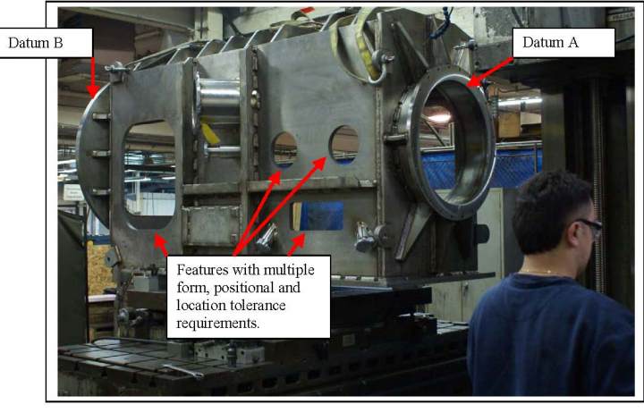
Figure 1. Illustration of Real World Object where GD&T defines the requirements.
To assist those unfamiliar with GD&T in gaining the basics, we plan to write a series of articles explaining basic concepts. We will start in the remainder of this article by discussing two concepts of GD&T that are key to understanding its use. The first is a simple but often misunderstood concept, the “Basic Dimension”, and a more involved subject, “Feature Control Frames”.
BASIC DIMENSION: Defined in Y14.5 as “A numerical value used to describe the theoretically exact size, profile, orientation, or location of a feature or datum target.” A basic dimension can be a rectilinear dimension, a diameter, an angle, etc. It is indicated on a drawing by a box around the dimension value as shown below.
BASIC DIMENSION: Defined in Y14.5 as “A numerical value used to describe the theoretically exact size, profile, orientation, or location of a feature or datum target.” A basic dimension can be a rectilinear dimension, a diameter, an angle, etc. It is indicated on a drawing by a box around the dimension value as shown below.
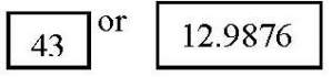
The key to the basic dimension is to understand it has no tolerance itself. As stated it represents the exact size, the number of digits to the right of the decimal place represent no implied or additional tolerance. The tolerance of a basic dimension is defined by the feature control frame associated with it.
FEATURE CONTROL FRAME: Defined in Y14.5 as “A geometric tolerance for an individual feature is specified by means of a feature control frame divided into compartments containing the geometric characteristic symbols followed by the tolerance.” The feature control frame is the long rectangular box, filled with smaller boxes that contain the specific sequence of symbols, tolerances and datum identifiers that define the tolerance of a basic dimension or geometric feature.
FEATURE CONTROL FRAME: Defined in Y14.5 as “A geometric tolerance for an individual feature is specified by means of a feature control frame divided into compartments containing the geometric characteristic symbols followed by the tolerance.” The feature control frame is the long rectangular box, filled with smaller boxes that contain the specific sequence of symbols, tolerances and datum identifiers that define the tolerance of a basic dimension or geometric feature.
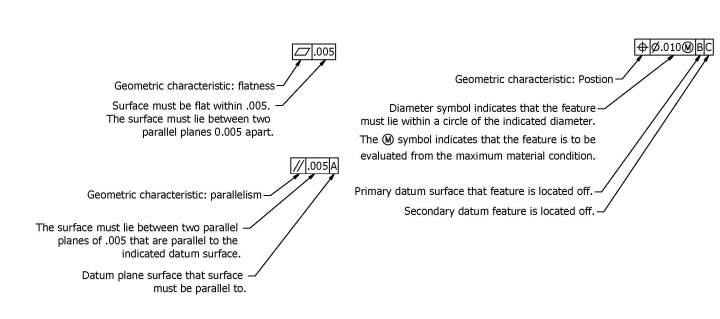
A feature control frame can apply to a single or multiple features. It must contain at minimum the geometrical characteristic symbol of form, orientation or position (e.g. true position, flatness, etc.) and a tolerance; they often contain tolerance modifiers (e.g. regardless of feature size, maximum material condition, etc.) and datum references. Feature control frames can be attached to a surface, axis or centerline. The method of attachment determines what feature(s) control is limited to. Like a well constructed sentence in a story, the feature control frame is used to communicate the full requirements to the reader. Once you have mastered the application and interpretation of feature control frames you will have learned the language of GD&T.
If this article was of interest to you, drop us a line and let us know. Your feedback will help us determine what type of content you would like to see in our newsletter and posted to the website.
If this article was of interest to you, drop us a line and let us know. Your feedback will help us determine what type of content you would like to see in our newsletter and posted to the website.