Call: 708-425-9080


Design and Fabrication Considerations for Stainless Steel Liquid Helium Jackets Surrounding SCRF Cavities
The Department of Energy requires its subcontractors (e.g. the National Laboratories) to meet 10 CFR 851 Appendix A Part 4 for all new pressure vessels and pressure piping. This requirement means all new Pressure Vessels are required to be built and stamped to the ASME Boiler and Pressure Vessel Code Section VIII and all new Pressure Piping is to be built to the appropriate ASME B31 Piping Code, which in most cases would be B31.3 Process Piping. When meeting these Codes is not possible, Section 4C allows the use of alternative rules which must provide a level of safety greater than or equal to these Codes.
The stainless steel pressure vessel boundaries surrounding SCRF cavities fall under this requirement. Laboratories have taken a variety of approaches to address this issue.4 One approach is to meet all design, fabrication, and non-destructive testing requirements required of the ASME Code and U or U2 stamp the helium jacket surrounding the niobium cavity.
Section VIII of the ASME Code consists of three Divisions: Division 1 “Rules for Construction of Pressure Vessels”, Division 2 “Alternate Rules”, and Division 3 “Alternative Rules for Construction of High Pressure Vessels”. Division 3 concerns itself with pressure vessels with design pressures (internal or external) generally above 10,000 psi and thus is not germane to this discussion. Division 2 was developed primarily to provide guidelines to the chemical and petrochemical industry for specifying pressure equipment with lower design margins but requires significantly higher non-destructive testing and documentation requirements.2 As Division 1 and 2 cover the same scope of pressure vessels, the lower design margins and the possibility of thinner component wall thickness has made the use of Division 2 attractive to designers for pressure vessels surrounding SCRF cavities.
Both Division 1 and 2 contain the following key statements, first “This Division contains mandatory requirements, specific prohibitions, and non-mandatory guidance for the design, materials, fabrication, inspection, testing and certification of pressure vessels and their associated pressure relief devices.”5
From this statement it is clear that the requirements of the Divisions must be taken as a whole; selective use of portions of the requirements violates the intent of the specification and its underlying safety basis.
The second key statement, “The Code does not address all aspects of these activities. Those aspects that are not specifically addressed should not be considered prohibited and shall be addressed by appropriate engineering judgment. Engineering judgment shall be consistent with the philosophy of this Division and such judgment shall never be used to overrule mandatory requirements or specific prohibitions of this Division.”5
This statement gives us some lee-way to use engineering judgment in situations, such as the design of the pressure vessels surrounding SCRF cavities, not envisaged by the authors of the Code. But again, it does not give us carte blanche to deviate from Code requirements. Conversely, some details allowed by the Code may not be appropriate for certain applications.
This article will attempt to provide some guidance to those unfamiliar with the Code for specifying an ASME Code Pressure Vessel for use as the liquid helium pressure container surrounding a SCRF cavity.
ASME Section VIII Division 1ASME Section VIII is a Safety Code. It provides a set of rules intended to ensure that pressure vessels are designed and constructed to a minimum set of requirements resulting in safe operation. Division 1 is written to cover a wide range of pressure vessel applications and is not intended to define all the design and construction details of a given type pressure vessel.2 The scope of Division 1 is contained in Part U; pressure vessels utilized to jacket SCRF cavities generally do fall within this scope.
A mandatory rule of Section VIII is all pressure boundary materials forming part of the ASME Code stamped vessel must be listed for use by the Division in Section II of the ASME Code. SCRF cavities are constructed of niobium which is not a material recognized by the ASME Code. In designing a pressure vessel surrounding a SCRF cavity, consideration must be given to the geometric scope of the vessel to eliminate the niobium material from the ASME Code pressure boundary. Outside the geometric scope of the ASME Code stamped vessel the Division 1 rules, including material restrictions, would not apply. This is not an unusual approach. A common example of this is a cryogenic heat exchanger where an internal copper cooling coil penetrates the external stainless steel vessel, but through geometric scope definition is not considered part of the ASME Code stamped pressure vessel. Of course it must be recognized that the niobium cavity (like the copper coil of the heat exchanger) is part of a pressure boundary and its design and the interfaces between it and the ASME Code stamped pressure vessel must be handled accordingly.
Division 1 Part U-1(e)(1) provides guidance on how to separate the inner SCRF cavity from the ASME Code vessel pressure boundary. This part contains two paragraphs that define possible approaches; the ASME Code vessel boundary ends at the “(a) welding end connection for the first circumferential joint for welded connections” or “(d) the first sealing surface for propriety connections”. While there are a wide range of niobium cavity configurations, ranging from Cornell style 500 MHz single cell cavities to spoke cavities and everywhere in between, generally the interface between the niobium cavity can be designed to accommodate a transition stainless steel component that can be welded to the ASME Code vessel and form the “first circumferential joint” or a “first sealing surface” utilizing a cold seal to define the geometric boundary of the ASME Code vessel such that the SCRF cavity is excluded.
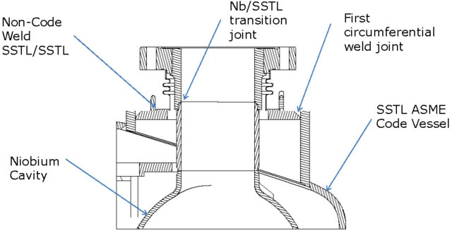
Figure 1. “First circumferential joint” design example. Argonne National Laboratory QWR Cavity Helium Jacket
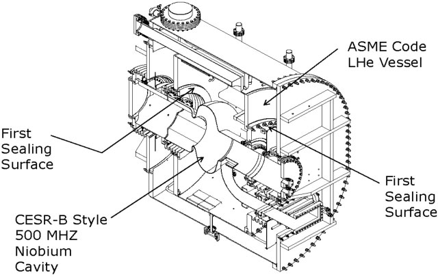
Figure 2. “First sealing surface connection” design example. CESR-B Style 500MHz Cavity Helium Jacket
While covering a range of applications, Division 1 does contain design and fabrication requirements pertaining to specific design conditions. The design characteristics of a typical stainless steel pressure vessel surrounding a SCRF cavity are listed in Table 1.
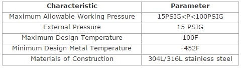
TABLE 1. Design Characteristics Typical SCRF Cavity Helium Pressure Vessel
Maximum Allowable Working Pressure: The maximum allowable working pressure (MAWP) or design pressure of the vessel is defined by UG-23 to be at least the most severe coincident combination of pressure and temperature expected in normal operation. Normal operation must consider transient conditions such as cool down, warm up, expected upset conditions, etc. The selected MAWP affects the selection of the pressure relief device which must be set to open at a pressure no higher than the MAWP. Thus to prevent relief during normal operating conditions the MAWP is normally defined at a percentage above the actual maximum operating pressure.
External Pressure: As the helium jackets surrounding SCRF cavities are often evacuated to vacuum during processing steps, the ASME design should include provision for 15 psig external pressure design. There are no special considerations other than those inherent in external pressure design according to Division 1.
Design Temperature: Unless driven by a processing step consideration, a design temperature of 100F would be the nominal choice. In ASME Section II, allowable stress values are temperature dependent and -20F to 100F is the first range and corresponds the to the largest allowable stress.
Minimum Design Metal Temperature: The minimum design metal temperature (MDMT) is the coldest temperature that is coincident with the maximum allowable working pressure. In the case of the helium jacket surrounding a SCRF cavity, this would be the operating temperature of the helium, normally 2K or 4K. The minimum design metal temperature affects the choice of suitable materials of construction, impact testing requirements, and requires the utilization of certain mandatory fabrication details.
Materials of Construction: Austenitic stainless steels, 304L or 316L, have been the material of choice for cryogenic ASME Code pressure vessels in the size and pressure range of SCRF cavity jackets. Due to magnetic permeation considerations 316L is more often the material of choice for SCRF cavity pressure jackets. 316LN has better magnetic permeation properties than 316L and is an ASME Section II material; however it is not readily available in the USA in product forms suitable for pressure vessel construction.
The selection of the MDMT and materials of construction have a direct affect on the determination of the level of impact testing required for the pressure vessel. General requirements for impact testing are contained in UG-84. However 304L and 316L materials fall under the requirements of Part UHA and the impact testing requirements of paragraph UHA-51. For those unfamiliar, the requirements of UHA-51 are difficult to navigate. Impact testing requirements can be exempted for the entire vessel or components of the vessel if the requirements of UHA-51(g) are met (discussed below). Otherwise with the MDMT being below -320F and the materials of construction being austenitic stainless steel, the impact test requirements are simplified if 316L weld filler metal with a ferrite number measured to be below 5 is used. (308L is allowed but with a ferrite number measured in the range of 4-14, which from practical experience is not available except by special order). While the allowable weld processes are restricted, for SCRF cavity pressure vessels it is unlikely that any weld process other than GTAW, PAW or GMAW, which are allowed, would be used. With these conditions, when impact tests are required, Charpy Impact tests are performed at -320F. Test coupons are required for all base material heats and production weld coupons to test base material, weld material and heat affected zone. Methods and specifics of the coupon and testing requirements plus acceptance criteria are discussed in UG-84 and UHA-51.
The requirement for impact testing leads to the often overlooked weld joint design requirements of UW-2(b). For UHA materials, such as 304L or 316L, where impact testing is a requirement: all Category A welds must be Type 1 per Table UW-12; all Category B welds must be Type 1 or 2 per Table UW-12 and all Category C and D welds must be full penetration welds extending through the entire section of the joint. Essentially all the welds on the pressure vessel are required to be full penetration welds when impact testing is required.
The provisions of U2-2(b) can make it attractive in some designs to utilize heavier component thicknesses that meet the exception criteria of UHA-51(g). Eliminating impact test requirements for the entire pressure vessel or a component of the vessel, would allow the use of weld joint details requiring less weld metal and the attendant distortion, leading to a more optimal fabrication solution.
Code Case 2695: This Code Case allows the use of Division 2 Part 4 “Design by Rule” methods to be utilized in the design of a pressure vessel or pressure vessel component on a Division 1 U stamped pressure vessel. Using the Division 2 methods may lead to thinner sections for formed heads and a reduction of reinforcement requirements.
There are restrictions to the use of this method. The most significant in regards to design of a pressure vessel for use in jacketing a SRCF cavity are: The lower tensile allowable stresses of Division 1 UG-23 must be used in the design calculations. The weld joint efficiency shall be determined per Division 1 UW-11 and UW-12. The establishment of weld joint efficiencies this manner will require that non-destructive examination (NDE) requirements are per Division 1 not Division 2. In Division 1 NDE requirements are predicated upon the selection of the weld joint efficiency. Material impact tests requirements and exemptions shall be per Division 1 requirements, however the low stress exemption for the ratio of coincident applied stress in tension to allowable tensile stress is per the Division 2 requirement of 0.24 not the Division 1 requirement of 0.35. If a shell section or formed head is sized per the Division 2 rules then all other features on that component will also have to be designed per the Division 2 rules. Weld joint details for the component must be per Division 2 requirements; this eliminates the use of details allowed under Division 1 but not Division 2. The fabrication tolerances of Division 2 must be followed.
ASME Section VIII Division 2Division 1 allowable stresses are based on specified minimum tensile strengths and a design margin of 3.5. The design margin of Division 2 is 2.4.2 The lower design margin, the Part 4 Design by Rule approach, and the option of Design by Analysis of Part 5 when design rules are not provided in Part 4, all make the use of Division 2 attractive to the designer of SCRF cavity pressure vessels. However with the possibility of thinner components come the more onerous documentation requirements of Part 2 Responsibilities and Duties and the additional Part 7 Inspection and Examination Requirements. The added costs and logistical requirements for meeting Part 2 and Part 7 alone may out weight fabrication advantages of designing to Division 2. This is without considering the fabrication details required by Division 2 that are more restrictive than Division 1.
Division 2 was rewritten for the 2007 edition of the Code, the current edition is 2010, the 2013 edition will be issued in July 2013. Division 2 consists of 9 parts which are discussed below in varying detail based on the importance to our discussion.
Part 1 General Requirements. This section is analogous to the Division 1 Part U. Paragraph 1.2.3 allows the same definition of geometric scope as in Division 1.
Part 2 Responsibilities and Duties. The requirement for the User’s, Manufacturer’s, and Authorized Inspector’s responsibilities and documentation requirements are clearly laid out in this section. The documentation requirements are extensive for both the User and the Manufacturer. The User is required to provide a “User’s Design Specification” that is certified by a registered professional engineer, the Manufacturer is required to develop a “Manufacturer’s Design Report” also certified by a different registered professional engineer. The requirements are much more extensive than those in Division 1, and require some engineering effort to compile and review. However most of the information, while not compiled in the same manner, would have been developed and documented to some extent under Division 1. This documentation is an additional cost in engineering and Authorized Inspector review resources not required in Division 1. Unless the fabrication advantages of designing to Division 2 are significant, from a cost standpoint, the additional engineering time might negate any expected fabrication savings.
Part 3 Material Requirements. There are differences in allowable materials between Division 1 and Division 2. For the materials of focus here, 304L and 316L product forms, this is not an issue. Obviously the allowable stress values contained in ASME Section II are higher. Part 3 also addresses impact test requirements. Paragraph 3.11.4 addresses “High Alloy Steels”. The only significant difference is in the low stress exemption for the ratio of coincident applied stress in tension to allowable tensile stress is 0.24”, lower than the 0.35 threshold in Division 1.
Part 4 Design by Rule Requirements. Part 4 contains the design rules for all the standard pressure vessel shapes. The load case combinations required to be reviewed are also provided. The Part requires thorough and complete reading, but is relatively easy to follow. When a component does not fall under a design rule, the stress analysis methods or Part 5 are to be used. A significant difference to Division 1 requirements that affects SCRF cavity pressure vessel design is the mandatory requirement in paragraph 4.2.5.2 (a) that all Category A welds must be Type 1 butt joints. (See Figure 3.) This prohibits the use of Type 2 butt joints with backing strips allowed by Division 1. The use of backings strips behind welds is an important fabrication detail used to both simplify fit up to interfaces on the SCRF cavity and to protect cavity surfaces during the welding of the pressure jacket. This prohibition will require careful consideration of weld joint locations and extreme care in welding execution. Section 4.2.5 “Types of Joints Permitted” which details the allowable weld joint details, potentially could have more of an effect on pressure vessel design than the component sizing rules. This section in conjunction with Part 7 will lead to the specification of the mandatory requirements for NDE of the welds, whether designed per Part 4 or Part 5.
Part 5 Design by Analysis Requirements. When a design rule in Part 4 is not available the design by analysis methods of Part 5 are employed. The failure modes and load cases to be investigated are very specific as is the methodology to follow. The details of the stress analysis, modeling, and verification are the responsibility of the designer/manufacturer. Either the rules in Part 4 Section 4.2 “Design Rules for Welded Joints” for the allowable weld joint details of Part 4 may be utilized with components designed under this Part or alternate weld details can be used if analyzed according to the methods of Part 5.
Part 6 Fabrication Requirements. General fabrication requirements for Division 2 vessels are contained in this Part. Points of interest for the design of SCRF cavity pressure vessels include: Additional requirements for material traceability and documentation, and clearer statement regarding the prohibition on backing strips for Type 1 welds (6.2.4.1). Details regarding the proper use of backing strips for Type 2 welds are located in paragraph 6.2.4.2.
Part 7 Inspection and Examination Requirements. The inspection and examination requirements that must take place during the construction of a Division 2 pressure vessel are detailed in Part 7. Inspection and examination requirements are much more extensive than Division 1. Requirements for visual examination of materials, component parts, in-process details, welding joint fit up, and finished welds are all covered. The use of Examination Groups to categorize the required NDE of welds is significantly different from Division 1. Selection of the proper Examination Group is based upon weld joint category, joint efficiency, and joint type. Table 7.2 details the required NDE for a given Examination Group. 304L or 316L materials of construction are categorized as P8 Group 1 materials, assuming the lowest weld joint efficiency (E=0.85) allowed, this leads to the selection of Examination Group 3b. This Examination Group requires a minimum of 10% radiography and 10% liquid penetrant testing of all welds on the pressure vessel. In general, due to logistics and handling concerns, SCRF cavity pressure vessels we’ve been involved with have been designed to avoid processes such as radiography.
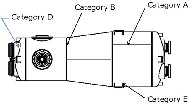
Figure 3. ASME Weld Categories Illustrated on the Argonne National Lab QWR Cavity Pressure Vessel
Part 8 Pressure Test Requirements. Depending upon subsequent processes, we have performed both hydrostatic and pneumatic tests on SCRF cavity pressure vessels. In both cases the pressure level requirements for testing are higher in Division 2 than in Division 1. In addition, if a pneumatic test is performed, the test must be monitored by acoustic emission examination per ASME Section V Article 12.
Part 9 Pressure Vessel Overpressure Protection. Information addressing pressure relief requirements are to be found in this Part. The details of how these requirements are to be met must be included in the Part 2 “User’s Design Specification” prior to the fabrication of the pressure vessel. It has been our experience that this information is often developed concurrently with the vessel fabrication or even after fabrication of the pressure vessel. Now it must be addressed by the User prior to fabrication.
ConclusionsBased on this review of ASME Section VIII Division 1 and Division 2 requirements in regards to stainless steel SCRF cavity pressure vessels we conclude the following.
References
Part 9 Pressure Vessel Overpressure Protection. Information addressing pressure relief requirements are to be found in this Part. The details of how these requirements are to be met must be included in the Part 2 “User’s Design Specification” prior to the fabrication of the pressure vessel. It has been our experience that this information is often developed concurrently with the vessel fabrication or even after fabrication of the pressure vessel. Now it must be addressed by the User prior to fabrication.
ConclusionsBased on this review of ASME Section VIII Division 1 and Division 2 requirements in regards to stainless steel SCRF cavity pressure vessels we conclude the following.
- Proper definition of the geometric boundary of the pressure vessel in relation to the niobium cavity will allow the ASME Code Stamping of the liquid helium containing pressure vessel jacket.
- ASME Code Stamping can be done to either Division 1 (U stamp) or Division 2 (U2 stamp).
- In order to Code Stamp a vessel, all the requirements, design, materials, documentation, fabrication, inspection, examination, and testing of the selected Division must be met, not just the design requirements.
- Division 1 design formulas and safety factors are more conservative than Division 2 requirements.
- Division 2 documentation, fabrication details, inspection, and examination requirements are more extensive and in some cases more restrictive than Division 1.
- Code Case 2695 allows the use (under prescribed conditions) of Division 2 Part 4 Design by Rule methods in the design of a Division 1 U stamped pressure vessel.
- In Division 1 designing to achieve the UG-54(g) low stress exemption to the impact test requirements can allow the selection of lower distortion weld details and simplify fabrication.
- In Division 2 the more restrictive mandatory weld joint details can complicate design for fabrication and fabrication sequencing requirements.
- The User/Designer has a number of technical and cost trade-offs to consider between choosing to Code Stamp a SCRF cavity pressure vessel to either Division 1 or Division 2. For low volume research and development assemblies, Division 1 seems the logical choice. For larger volume production assemblies the choice is less clear.
References
- T. P. Paster, “Section VIII: Division 1-Rules for Construction of Pressure Vessels,” in Companion Guide to the ASME Boiler & Pressure Vessel Code, edited by K. R. Rao, American Society of Mechanical Engineers, 2012, pp. 139-196.
- D. A. Osage, C. D. Rodery, G. G. Karcher, T. P. Paster, R.G. Brown, and P. A. Henry, “Section VIII: Division 2-Alternate Rules,” in Companion Guide to the ASME Boiler & Pressure Vessel Code, edited by K. R. Rao, American Society of Mechanical Engineers, 2012, pp. 139-196
- E. C. Bonnema, "Information on the ASME Code and DOE Pressure Safety Rules", Meyer Tool Newsletter, July 2009.
- T. J. Peterson, H. Hayano, K. Jensch, E. Kako, A. Klebaner, J. Mammosser, A. Matheisen, H. Nakai, T. Nicol, J. Theilacker, A. Yamamoto, "A Survey of Pressure Vessel Code Compliance for Superconducting RF Cryomodules", FERMILAB-PUB-11-252-AD-TD, September 2012.
- ASME Boiler and Pressure Vessel Code, Section VIII, Division 1 & 2, American Society of Mechanical Engineers, 2010 Edition.