Call: 708-425-9080
Case Study: MINERvA Detector Cryostat - A Challenge in Helium Leak Detection
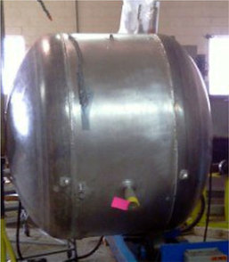 Liquid Helium Vessel
Earlier this month, we received a kind email from Bob Sanders of Fermilab letting us know that the MINERvA experiment detector cryostat Meyer Tool had built for Hampton University was successfully installed in Fermilab’s MINOS experimental hall. The 2300 liter helium cryostat is being kept cold by a 1.5 W cryocooler, with a significant amount of refrigeration capacity left over. While the cryostat has not yet reached steady state operating conditions and Fermilab has hasn't had a chance to calculate the actual heat load, Bob's note made it clear that the heat load is expected to be well below the 1.5W capacity of the cryocooler.
Bob’s email reminded us of some of the challenges the fabrication of the MINERvA detector cryostat presented; some were unique to the vessel itself, while others were typical of cryostat vessels in general. The foremost of these challenges was tracing the origin of an elusive 1x10⁻⁷ std-cc/sec (helium) leak discovered in what was to be the final test of the vessel before crating and delivery.
The MINERvA detector cryostat is an experimental collaboration between Hampton University and Fermilab. Meyer Tool received a partially complete set of drawings and was tasked with performing design calculations, developing the final fabrication details and manufacturing the cryostat. Meyer Tool Senior Project Manager, Tony Vouris, was in charge of the project. “The MINERvA cryostat was more difficult to assemble than your typical cryostat. The entire cryostat was fabricated almost entirely from the thinnest aluminum possible, the inner helium vessel and aluminum shield were supported by para-aramid (Kevlar™) straps. The tight spacing between the vacuum vessel, shield assembly, and inner helium tank, required a precise assembly plan,” said Mr. Vouris.
The cryostat consisted of three main subassemblies including the horizontally configured aluminum vacuum vessel, the thermal shields and the internal liquid helium aluminum pressure vessel.
The internal liquid helium pressure vessel was designed and stamped to the ASME B&PV Code Section VIII Division 1. The vessel was fabricated from 6061-T6 with 5083-O aluminum heads. A horizontal vessel 60” diameter with a 59.25” overall length, the pressure vessel has two 2:1 ellipsoidal heads at either end. The vessel was designed for a maximum allowable working pressure of 45 psig with a full external vacuum. To ensure the best possible transmission of the NuMI neutrino beam into the detector, the vessel was designed to provide the thinnest possible wall thickness in the heads, while meeting the pressure and vacuum design requirements. The vessel had only three nozzles, one for liquid helium inlet, one for gaseous helium outlet, and one larger instrumentation line.
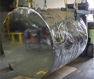 Minerva Helium Vessel Shield Assembly
he liquid helium in the inner vessel is kept cool by a 1.5 W cryocooler. Design features to minimize conductive and radiative heat transfer were employed. The inner liquid helium vessel was insulated with a 20 layer double aluminized mylar/polyester spacer superinsulation blanket. The thermal shield was also insulated with a 20 layer superinsulation blanket. Both the helium vessel and the thermal shield were supported off the vacuum vessel using para-aramid straps. The only other conductive paths in the vessel design were the cryogen lines, instrumentation line, and the cryocooler connections.
In process helium leak testing and pneumatic pressure testing of the components took place at appropriate points. The liquid helium vessel was pressure tested according to the requirements of the ASME code and then leak tested. The helium vessel was cold shocked prior to testing.
In process helium leak testing and pneumatic pressure testing of the components took place at appropriate points. The liquid helium vessel was pressure tested according to the requirements of the ASME code and then leak tested. The helium vessel was cold shocked prior to testing.
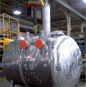
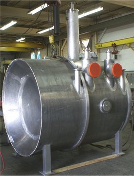 MINERvA Cryostat
The design called for a completely welded assembly with access to the cryogen lines through a single combined port on the vacuum vessel and a separate stack for the instrumentation line with an access flange exterior to the vacuum space. Thus, to begin assembly, the vacuum vessel was welded and leak tested with just the reverse head un-welded to the shell and the instrumentation stack to be completed. The tested helium vessel was insulated with superinsulation and the support straps installed. The helium vessel was then installed in the partially welded thermal shield and the thermal shield welded shut around it. The helium vessel’s support straps were routed outside the thermal shield. Twenty layers of superinsulation were then installed over the thermal shield and the thermal shield support straps. We supported this assembly by the helium vessel and thermal shield thermal straps on a fixture support designed by Meyer Tool to allow the entire assembly to be telescoped into the 98” long vacuum vessel. With this installation accomplished, the thermal shield/helium vessel assembly support straps were connected to the vacuum vessel and the fixture was removed. Once connected to the vacuum vessel, the internal assembly was located laterally within the vacuum vessel and leveled by drawing in the strap lengths.
The reverse head was then fit to the vacuum vessel and welded. This completed the vacuum vessel encasement of the inner assembly, but not all the necessary welding. To allow the inner assembly to fit into the vacuum vessel, the cryogen and instrumentation lines were left as short stubs. Once assembled, the lines needed to be lengthened to allow access for connection. Subassemblies of stainless steel with bimetal stainless steel-aluminum transitions were made, cold shocked and helium leak tested on the bench. Thus each line, liquid helium in, gaseous helium out and the instrumentation line, had one aluminum to aluminum out of position weld to be made. These welds were made, the new joints cold shocked and leak tested, and the final shielding and superinsulation work completed.
All of the above was smoothly completed and the stage set for the final test before shipping.
In this final test, a standard test performed on all cryostats built by Meyer Tool, the vacuum vessel is evacuated and connected to a helium leak detector. Interior cryogen circuits and vessels, in this case just the helium vessel, are separately pressurized with helium gas. In this highly sensitive test (the system sensitivity was in the 10-10 std-cc/sec range) any leaks will be discovered. Generally this test is anticlimactic and we proceed to prepare the cryostat for shipment. But not this time!
As we increased the test pressure of the helium gas within the helium vessel to about 30 psig, we started to detect a very small 10-7 range leak! This is the worst type of leak to happen; not only is it small, but it is also pressure sensitive. This means that the leak would likely be undetectable under normal leak testing conditions (the interior of the component evacuated and spraying the outside with helium gas).
Our engineering and leak testing teams sat down to discuss next actions. There would be no easy access for testing; the combined nozzle containing the cryogen lines was accessible but the instrumentation stack was the usual layered assembly of superinsulation, shielding and inner line. It was a welded assembly.
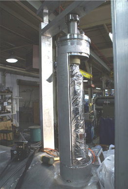 Accessing the Instrumentation Line
First, we listed in order of probability where the leak could be occurring. We had two VCR joints, three out of position final welds, three bimetal fittings, a bellows in the instrumentation stack, other welds in the access port area and instrumentation stack, and welds in the vessel itself. We developed a sequential plan to eliminate possibilities. We understood it would be a long and frustrating process, but we were optimistic we would identify the leak’s location. Over the course of several weeks, we painstakingly eliminated possibilities through repeated testing while eliminating variables. First we eliminated the mechanical joints (the VCR fittings).Then, through measuring the response time of the leak detector, we eliminated the vessel itself as the source. Finally, through bagging and accumulation techniques utilizing the sniffer probe method, we narrowed it to a section of the instrumentation line containing an out of position final weld, a length of aluminum tubing, a bimetal joint, and a length of stainless steel tubing. We couldn’t narrow it down any further. We cut the section out below the lower weld, so the entire out of position weld was included in the removed section. We ordered replacement bimetal and remade the section.
Before re-installing the replacement section, we temporarily welded a blank-off plate to the line from the vessel. We then performed another test.
Success! We had located (at least within the section) the leak. We were able to install the replacement section and successfully and easily confirm the vessel was pressure and leak tight.
But the story isn’t complete, where was this tiny, pressure sensitive leak?
We took the section we had cut out and welded caps on the end. We repetitively cold shocked it in an attempt to increase the size of the leak. We pressure cycled it, again to try to increase the leak. After numerous attempts on the bench to locate the leak, we finally found it. It wasn’t in the VCR fitting seal, a weld, or the bimetal joint. The leak was in the parent metal of the aluminum material used to make the bimetal joint.
A highly unusual occurrence, a pressure sensitive leak in plate material. The leak was likely due to a lamination in the plate. Under the stress of repeated cold shocks and testing, the flaw, although tiny, opened up under pressure and only could be detected by the highly sensitive final test of the cryostat. Only after more repeated cold shock and pressure cycles were we able to cause the leak to be detectable when the interior of the section was under vacuum and while we painstakingly went over the surface of the piping section with a minimal helium flow to locate the flaw.
When we received Bob’s email telling us the Detector Cryostat was installed and performing better than expected, we were doubly pleased. It is gratifying to receive this type of feedback. It validates our mission to provide customers with the Lowest Total Cost of Ownership.


