Call: 708-425-9080
Aluminum Anodizing and Vacuum Chambers
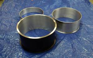
 Externally Anodized Vacuum Chamber shown with internal shields unanodized.
Aluminum is often used to fabricate vacuum vessels, either as a "hog-out" or as a weldment. Anodizing of aluminum vacuum chambers is sometimes specified. This article explores what anodizing is and how it can affect a vacuum chamber.
The anodizing of aluminum is achieved through the controlled electrochemical application of an aluminum oxide coating to raw aluminum. The oxide layer, a few thousands of an inch in thickness, forms a harder, more abrasive and corrosion resistant surface than the raw aluminum. The oxide layer is also non-conductive. The oxide layer is clear unless otherwise treated. Immediately upon removal from the anodizing tank the oxide film is still porous and may be colored through the application of dye, electrolytic deposition of metal salts or a combination of these processes.
The anodizing of aluminum is achieved through the controlled electrochemical application of an aluminum oxide coating to raw aluminum. The oxide layer, a few thousands of an inch in thickness, forms a harder, more abrasive and corrosion resistant surface than the raw aluminum. The oxide layer is also non-conductive. The oxide layer is clear unless otherwise treated. Immediately upon removal from the anodizing tank the oxide film is still porous and may be colored through the application of dye, electrolytic deposition of metal salts or a combination of these processes.
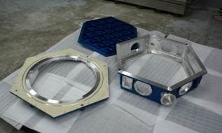
 Externally Anodized Vacuum Chamber, blue.
The basic anodizing process follows these steps:
Type I:
Chromic acid anodizing, conventional coatings produced from chromic acid bath.
Type IB:
Chromic acid anodizing, low voltage process.
Type II:
Sulfuric acid anodizing, conventional coatings produced from sulfuric acid bath.
Type III:
Hard Anodic Coatings.
Class 1:
Non-dyed, natural, including dichromate sealing.
Class 2:
Dyed.
For vacuum vessels, Type I or II are commonly specified for external corrosion resistance. Appearance can often be less than ecstatic, especially in weldments. Type II Class 2 is often specified for external decorative purposes. Type III is used for internal and external abrasion or wear resistance, dielectric resistance, and decorative purposes when Class 2 is specified. Again appearance is more uniform in non-welded chambers as the differing chemistry between the base and weld metals in welded chambers causes the weld zones to take on a lighter hue than the base metal.
As the oxide layer is added to the existing material, the dimensions of highly toleranced features can be affected. This is most commonly noted in threaded holes and holes for pins. Allowance must be made prior to anodizing or the threaded holes re-tapped and pin holes reamed after anodizing. Of course these post anodizing processes remove the oxide layer.
Anodizing aluminum greatly increases the outgassing rate of the aluminum. Appendix C.2 in O’Hanlon, A User’s Guide to Vacuum Technology, lists outgassing rates for unbaked metals at 1 hour and 10 hours. Aluminum (3 hours in air) is listed as 88.6 x 10⁻⁷ W/m2 at 1 hour, anodized aluminum is listed at 3679 x 10-7 W/m2, a 41 times greater outgassing rate. At 10 hours the outgassing rate of aluminum is listed at 6.33 x 10⁻⁷ W/m2, while anodized aluminum is at 71 times that rate at 429 x 10-7 W/m2. These numbers values should be taken as relative guidelines between raw aluminum and anodized aluminum. The actual outgassing rates of real components could vary widely from these values.
The outgassing load is a component of the vacuum vessel’s total gas load. The total load consists of the residual gas from initial atmospheric pressure pump-down, the vapor pressure of materials in the chamber, leakage, permeation and the outgassing. The outgassing values as given by a source such as O’Hanlon are used to determine step-wise gas loads which are added to the ideal pump-down gas load for calculating the pump-down curve. The mechanics of developing the pump-down curve are involved and beyond the scope of the present discussion.
So what can we say is the practical effect of these huge differences in outgassing values?
The ultimate pressure of a vacuum system is directly proportional to the outgassing load. The general observation is that when chamber geometry (surface area) and pumping speed are held constant for a chamber design, a chamber fabricated from anodized aluminum will take much longer to reach the desired ultimate pressure (assuming the pumping speed is sufficient) than one fabricated from raw aluminum.
Using an internally anodized aluminum vacuum chamber for an application in the 10-5 torr range is a matter of balancing your vacuum pumping system and desired pump times versus the expected increase in outgassing rate.
Using internally anodized vacuum chambers in higher vacuum regimes becomes more challenging, but again involves determining the cost/benefits of the trade-offs between the need driving the anodizing and alternate methods such as low outgassing paints versus the cost in pumping system or bake out and pump down times. At Meyer Tool our engineering staff can assist you in determining what your options are to Reduce Project Risk and achieve your lowest total cost of ownership.
- Mechanical surface preparation.
- Masking if required.
- Chemical surface preparation, cleaning and etching in the appropriate chemical bath.
- Application of the direct current in a chromate or sulfuric acid bath depending upon type specified. This is the actual anodizing process to form the porous aluminum oxide coating.
- Either a dye application to allow the dyes to absorb into the porous aluminum oxide surface or the application of an alternating current to allow the deposition of metal salts into the bottom of the porous oxide film. Both techniques are done to color the layer.
- Final sealing of the oxide film pores through application of hot water, chemicals, or electrical deposition of an acrylic solution.
Type I:
Chromic acid anodizing, conventional coatings produced from chromic acid bath.
Type IB:
Chromic acid anodizing, low voltage process.
Type II:
Sulfuric acid anodizing, conventional coatings produced from sulfuric acid bath.
Type III:
Hard Anodic Coatings.
Class 1:
Non-dyed, natural, including dichromate sealing.
Class 2:
Dyed.
For vacuum vessels, Type I or II are commonly specified for external corrosion resistance. Appearance can often be less than ecstatic, especially in weldments. Type II Class 2 is often specified for external decorative purposes. Type III is used for internal and external abrasion or wear resistance, dielectric resistance, and decorative purposes when Class 2 is specified. Again appearance is more uniform in non-welded chambers as the differing chemistry between the base and weld metals in welded chambers causes the weld zones to take on a lighter hue than the base metal.
As the oxide layer is added to the existing material, the dimensions of highly toleranced features can be affected. This is most commonly noted in threaded holes and holes for pins. Allowance must be made prior to anodizing or the threaded holes re-tapped and pin holes reamed after anodizing. Of course these post anodizing processes remove the oxide layer.
Anodizing aluminum greatly increases the outgassing rate of the aluminum. Appendix C.2 in O’Hanlon, A User’s Guide to Vacuum Technology, lists outgassing rates for unbaked metals at 1 hour and 10 hours. Aluminum (3 hours in air) is listed as 88.6 x 10⁻⁷ W/m2 at 1 hour, anodized aluminum is listed at 3679 x 10-7 W/m2, a 41 times greater outgassing rate. At 10 hours the outgassing rate of aluminum is listed at 6.33 x 10⁻⁷ W/m2, while anodized aluminum is at 71 times that rate at 429 x 10-7 W/m2. These numbers values should be taken as relative guidelines between raw aluminum and anodized aluminum. The actual outgassing rates of real components could vary widely from these values.
The outgassing load is a component of the vacuum vessel’s total gas load. The total load consists of the residual gas from initial atmospheric pressure pump-down, the vapor pressure of materials in the chamber, leakage, permeation and the outgassing. The outgassing values as given by a source such as O’Hanlon are used to determine step-wise gas loads which are added to the ideal pump-down gas load for calculating the pump-down curve. The mechanics of developing the pump-down curve are involved and beyond the scope of the present discussion.
So what can we say is the practical effect of these huge differences in outgassing values?
The ultimate pressure of a vacuum system is directly proportional to the outgassing load. The general observation is that when chamber geometry (surface area) and pumping speed are held constant for a chamber design, a chamber fabricated from anodized aluminum will take much longer to reach the desired ultimate pressure (assuming the pumping speed is sufficient) than one fabricated from raw aluminum.
Using an internally anodized aluminum vacuum chamber for an application in the 10-5 torr range is a matter of balancing your vacuum pumping system and desired pump times versus the expected increase in outgassing rate.
Using internally anodized vacuum chambers in higher vacuum regimes becomes more challenging, but again involves determining the cost/benefits of the trade-offs between the need driving the anodizing and alternate methods such as low outgassing paints versus the cost in pumping system or bake out and pump down times. At Meyer Tool our engineering staff can assist you in determining what your options are to Reduce Project Risk and achieve your lowest total cost of ownership.


