Call: 708-425-9080


Brazed Joints at the Vacuum Boundary
Occasionally dissimilar metals must be joined to form a vacuum boundary in a chamber or assembly. When the joint is to be a permanent joint, brazing is the most common method utilized to make the joint. This article discusses some fundamentals of brazing and illustrates it use in vacuum and cryogenic applications. In our first example in the photo below, a water cooled copper cooling block is within the vacuum space, as it is brazed to an opening in the side wall of a UHV chamber used in an industrial electron accelerator. The water channel cover and inlet outlet lines are also brazed joints.
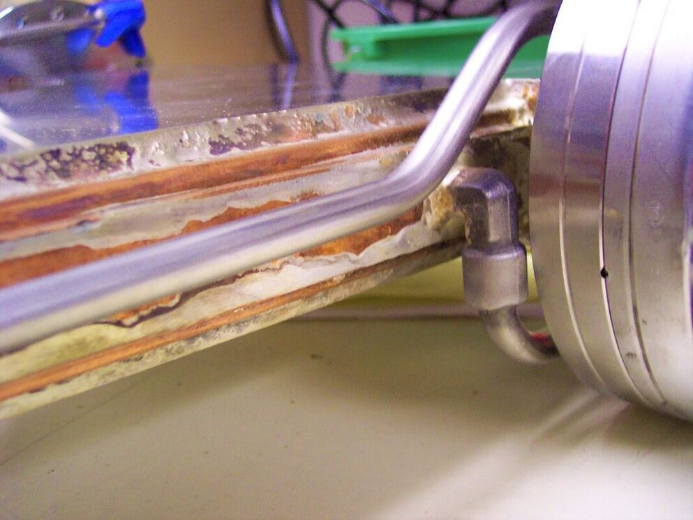
Accelerator Beam Line Vacuum Chamber with Cooper Cooling Block Brazed to Stainless Steel Chamber
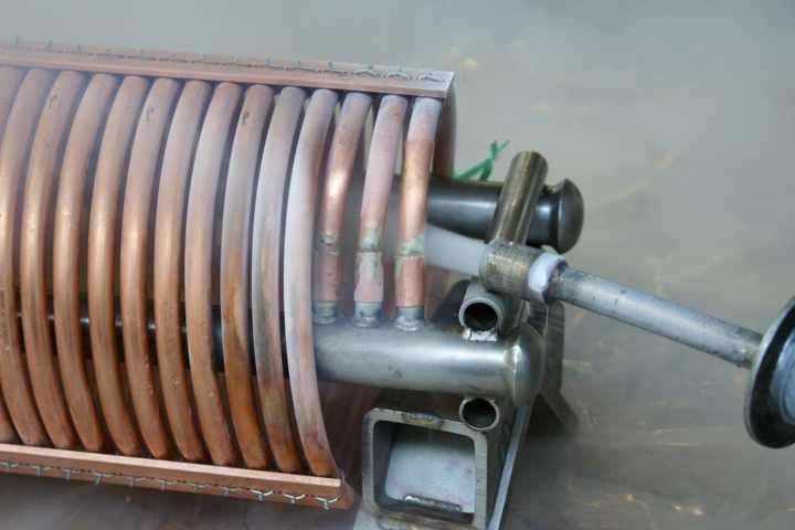 Torch Brazed Copper-SSTL HX Brazement
Brazing is a metal joining process in which: the parts (base metals) to be joined are heated without exceeding their melting temperature; the braze filler metal is melted at a temperature above 840°F; and the braze filler metal wets the base metal surfaces and is drawn or held in the joint by capillary action.
Selection of the proper brazing process for a particular application depends on an understanding how the variables involved can affect the process. Variables common to all brazing processes are the base metals to be brazed and the heating method selected, these in turn affect the choice of joint design, surface finishes, fixture design, flux or atmosphere choice, and the braze filler metal.
The three most common brazing process heating methods are torch brazing, furnace brazing and induction brazing.
Torch brazing uses a flame from an air-fuel gas mixture, commonly oxyacetylene. A brazing flux is used to clean the base metals and prevent oxidation prior to brazing. Heat is applied uniformly to the area to be brazed such that the flux and filler metal melt and wet the surfaces to be joined. Manual control of the flame and heat application by an experienced operator is key to a successful leak tight joint. Proper cleaning of the flux from the parts must take place immediately after brazing. This is critically important for vacuum applications, where acid flux can both out-gas and over time degrade the joint. In the photo above the copper-stainless steel were brazed using a high silver bearing alloy. The cooper heat exchanger coils and stainless steel headers hold a pressurized cryogen gas eventually cooled by the surrounding cryogen liquid bath in the stainless steel shell that the coils will be assembled to. Testing of the joints includes liquid nitrogen 'cold shocking' to subject the joints to the stresses of rapid cooling and warming prior to pressure and helium leak testing.
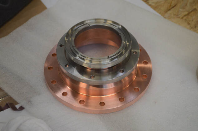 Furnace Brazed Copper-Stainless Steel UHV Transition
Furnace brazing utilizes, not surprisingly, a furnace with calibrated controls that ramp and maintain temperature, atmosphere and rates. There are a wide variety of brazing furnaces; the types most used for vacuum components utilize a vacuum, neutral or reducing atmosphere. Proper selection of other variables can eliminate the need for a flux in furnace brazing processes. This is an advantage for vacuum applications. In general furnace brazing will be more costly for single or low volume applications than torch brazing.
The photo to the left illustrates a common application in UHV, a copper to stainless steel transition. Vacuum furnace brazed using a silver brazing alloy, the transition must pass helium leak testing with acceptance criteria of 1x10⁻¹⁰ mbar-l/sec.
Induction brazing equipment utilizes a high frequency current to heat the joint area which is placed in a coil sized to the assembly’s geometry. This method of heating is chosen when rapid, highly local heating of the joint area is necessary. This may be due to the size of the part; that other forms of heating will cause distortion; or a desire to avoid changing material properties of the component in areas outside the joint.
Filler Metal: The American Welding Society (AWS) defines brazing filler metal rather simply as “the metal added when making a braze; with a melting point above 840F and below that of the base metals to be joined”. The AWS and the ASME Code utilize the same classification system to characterize brazing filler metals by their chemical composition. A useful selection guide a can be found in Section II Part C SFA-5.8 of the ASME Code. For vacuum and cryogenic applications the BAg-xx series of silver brazing alloys are the most common for copper to stainless steel applications. BAu-xx (gold alloys) while more expensive are also used.
Flux or atmosphere selection: For the dissimilar metal combinations encountered in vacuum applications, a flux must be employed when the joint is made in atmosphere, as in torch brazing. Brazing flux is a chemical mixture that is applied during brazing to shield the joint surface from air and prevent the formation of oxides. The selection of the proper flux is a function of the braze filler metal selection and base metals. Immediately after completion of the braze joint the remaining flux must be removed. The best method, if possible, is to quench and soak the assembly in hot water. A useful selection guide a can be found in Section II Part C SFA-5.3.1 of the ASME Code.
A controlled atmosphere, like brazing flux, is used to prevent the formation of oxides during the brazing process. Utilized during a furnace brazing process, the selection of the proper atmosphere is driven by filler metal and base metal considerations. The wrong atmospheric selection could interact with the metals.
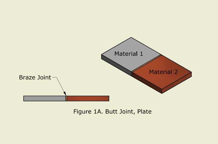
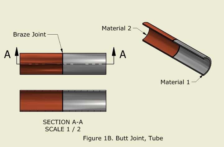
Joint Design: There are only two basic braze joint types, the butt joint and the lap joint. All other designs are variations on these two basic designs. The joint types are illustrated in Figures 1A through 2B.
Butt joints are rarely used in vacuum boundary applications and are not recommended. Butt joints are limited in strength to the contact area formed by the thickness of the base metal parts and provide only a small braze area with greater possibility for leakage.
Flux or atmosphere selection: For the dissimilar metal combinations encountered in vacuum applications, a flux must be employed when the joint is made in atmosphere, as in torch brazing. Brazing flux is a chemical mixture that is applied during brazing to shield the joint surface from air and prevent the formation of oxides. The selection of the proper flux is a function of the braze filler metal selection and base metals. Immediately after completion of the braze joint the remaining flux must be removed. The best method, if possible, is to quench and soak the assembly in hot water. A useful selection guide a can be found in Section II Part C SFA-5.3.1 of the ASME Code.
A controlled atmosphere, like brazing flux, is used to prevent the formation of oxides during the brazing process. Utilized during a furnace brazing process, the selection of the proper atmosphere is driven by filler metal and base metal considerations. The wrong atmospheric selection could interact with the metals.
Joint Design: There are only two basic braze joint types, the butt joint and the lap joint. All other designs are variations on these two basic designs. The joint types are illustrated in Figures 1A through 2B.
Butt joints are rarely used in vacuum boundary applications and are not recommended. Butt joints are limited in strength to the contact area formed by the thickness of the base metal parts and provide only a small braze area with greater possibility for leakage.
|
|
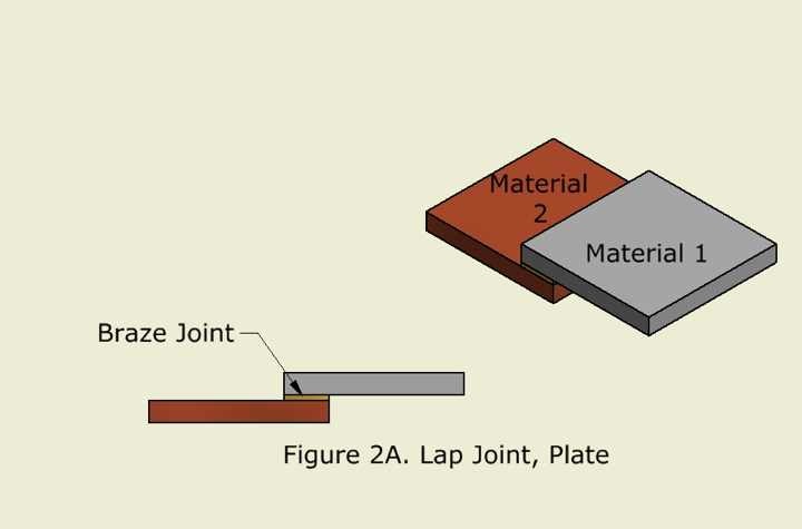
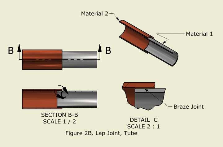
Lap joints are recommended for vacuum boundary applications. The lap can be designed to increase joint strength (by increasing the overlap) and provide a large braze area where minor imperfections (voids) will not lead to a leak. All joint designs should use correct clearances (taking into account coefficients of thermal expansion for dissimilar metals), proper machining details to avoid the formation of flux traps within the joint, and provision for venting of brazing gasses and the flow of flux out of the joint. Ideally a joint design that allows visual conformation that the braze filler metal has completely flowed through the joint is desired.
|
|
Surface Finishes: Braze filler metal is drawn into the joint clearance by capillary action. A too smooth surface finish may prevent even distribution of the filler metal in the joint. This could result in voids in the joint that will lower its strength. Too rough a surface finish has a similar effect, by increasing the average clearance at the low points of the finish. The AWS recommends a surface finish on the base metals between 30 and 80 micro-inches RMS for most applications.
Fixture Design: The best type of fixturing is component and joint design that allow for self-fixturing of the components to be brazed through assembly. Unfortunately this is not always possible. A few principles to keep in mind when designing braze fixtures are:
The experienced engineers and manufacturing staff at Meyer Tool have the knowledge and experience to assist you in the determining the best choices for your brazing application. This knowledge ensures product quality and is just one aspect of how we apply our Reduce Project Risk Process to your aluminum chamber requirements. Meyer Tool has more than 50 years of experience manufacturing cutting-edge components and assemblies. Our experience spans a wide range of materials, processes, and project sizes. Whether you’re building a single prototype or need production manufacturing support for your unique components, Meyer Tool’s engineering and manufacturing team approaches each challenge using our Reduce Project Risk Process to support your needs.
Working on a project that requires manufacturing expertise?
Give us a call at 708-425-9080 or fill out our RFQ form to get started!
Fixture Design: The best type of fixturing is component and joint design that allow for self-fixturing of the components to be brazed through assembly. Unfortunately this is not always possible. A few principles to keep in mind when designing braze fixtures are:
- The parts to be brazed must be kept in a fixed position that is maintained through the brazing process.
- Joint clearance must be maintained.
- Coefficients of thermal expansion, especially for dissimilar metals must be taken into account.
- The thermal mass of the fixture and its effect on the process.
- Keep it simple.
The experienced engineers and manufacturing staff at Meyer Tool have the knowledge and experience to assist you in the determining the best choices for your brazing application. This knowledge ensures product quality and is just one aspect of how we apply our Reduce Project Risk Process to your aluminum chamber requirements. Meyer Tool has more than 50 years of experience manufacturing cutting-edge components and assemblies. Our experience spans a wide range of materials, processes, and project sizes. Whether you’re building a single prototype or need production manufacturing support for your unique components, Meyer Tool’s engineering and manufacturing team approaches each challenge using our Reduce Project Risk Process to support your needs.
Working on a project that requires manufacturing expertise?
Give us a call at 708-425-9080 or fill out our RFQ form to get started!